
Apparatus and method for plasma synthesis of graphitic products including graphene

a plasma synthesis and graphene technology, applied in plasma techniques, separation processes, chemical/physical/physicochemical processes, etc., can solve the problems of requiring vacuum or low pressure operation, affecting the market of a wide and versatile range of graphene applications, and affecting the synthesis efficiency of graphene products. , to achieve the effect of reducing carbon deposition and ensuring gas flow

Pending Publication Date: 2017-04-27
LEVIDIAN NANOSYSTEMS LTD
View PDF11 Cites 25 Cited by
  • Summary
  • Abstract
  • Description
  • Claims
  • Application Information

AI Technical Summary

Benefits of technology

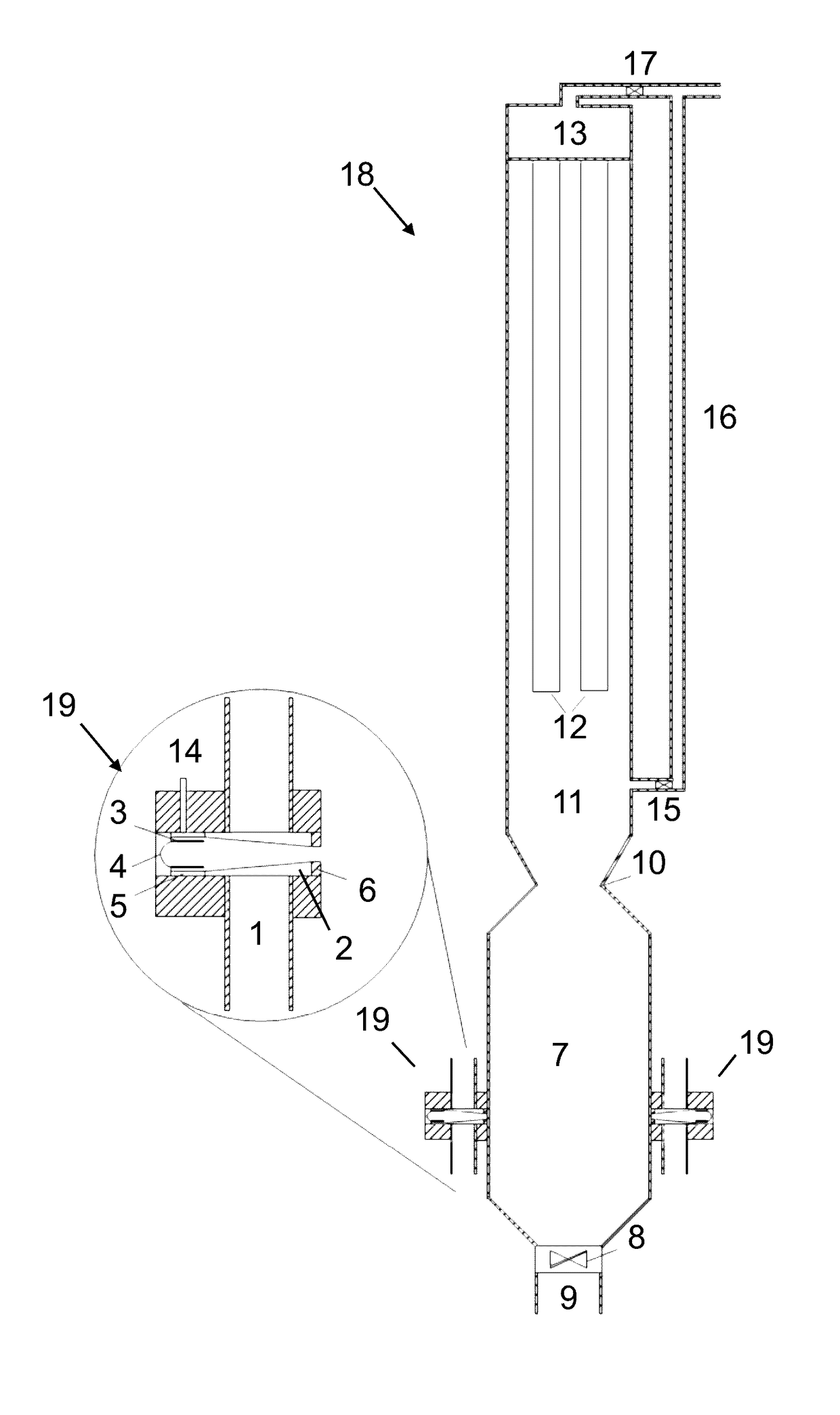
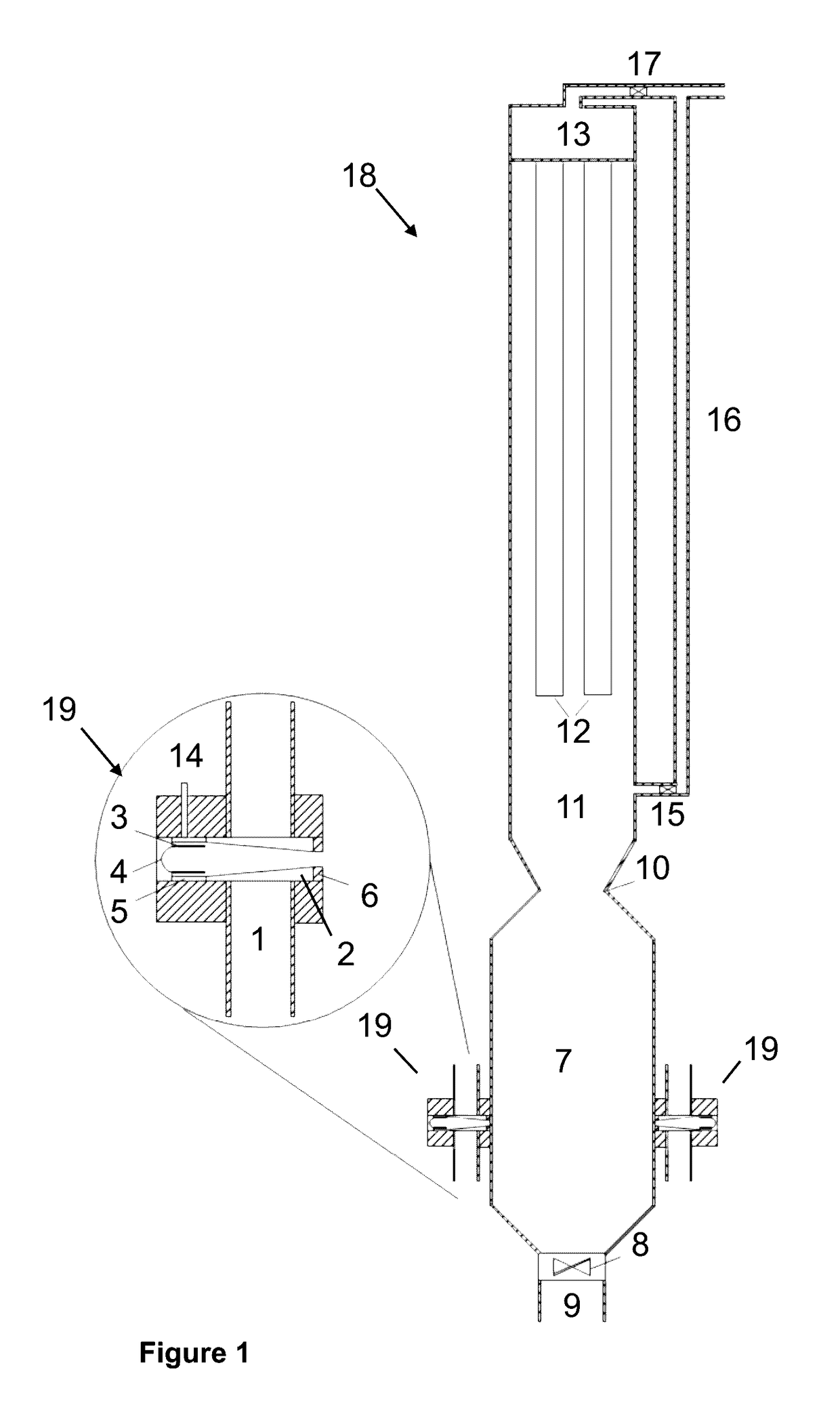
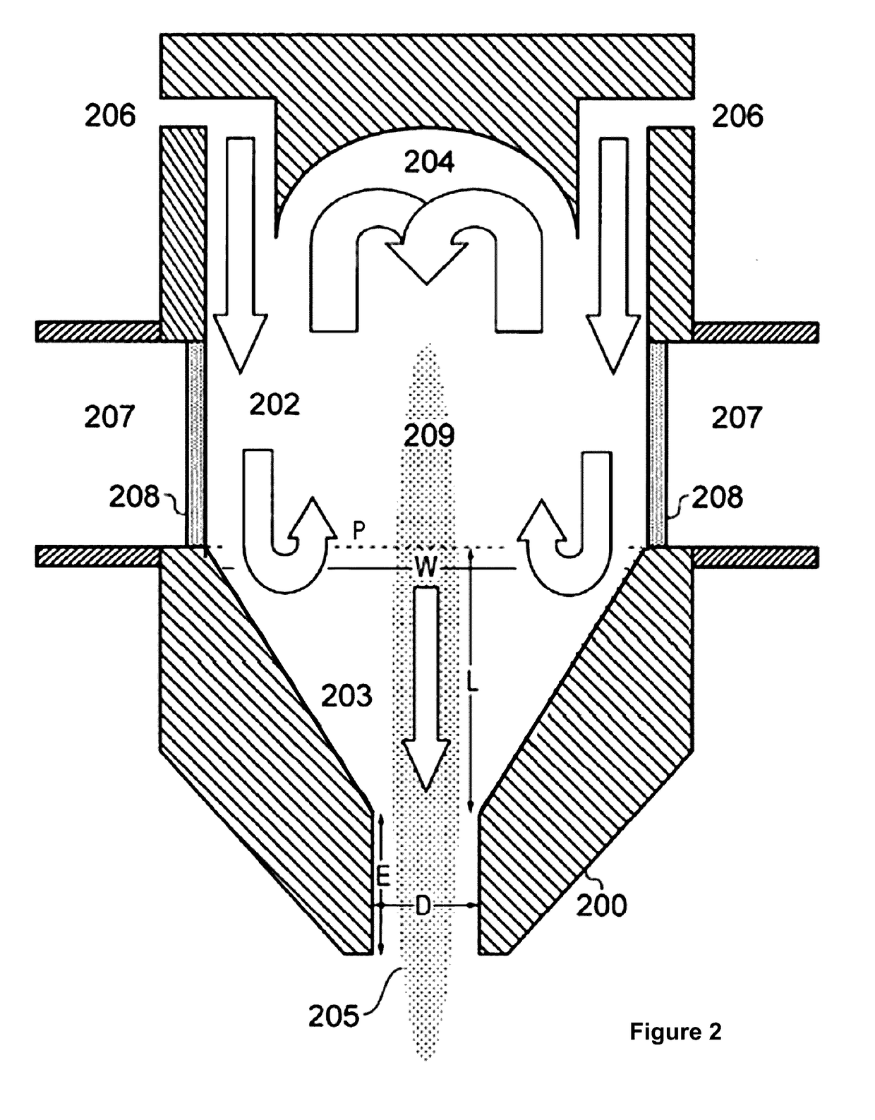
This patent describes a method for producing graphene on a large scale using a plasma reactor. The plasma nozzle is designed to create an afterglow of plasma that extends into the reaction chamber, which allows cracked carbon species to pass through and recombine, resulting in the formation of graphene. The use of multiple vortices increases the efficiency and stability of the plasma cracking process. The plasma is generated at atmospheric pressure, making operation easier. The nozzle interface with the reaction chamber is designed to reduce carbon build-up by maintaining a chord central angle greater than 0%. The apparatus may also include means to deliver gas around the interface to continuously minimize carbon deposition. Overall, this method provides a scalable and efficient means for producing graphene.

Problems solved by technology

However, the market of a wide and versatile range of graphene applications may be impeded as a large scale and cost efficient graphene production method is currently lacking.
However, these plasmas require vacuum or low pressure operation or high purity graphite electrodes with a complicated cooling system.

Method used


Image

  • Apparatus and method for plasma synthesis of graphitic products including graphene
  • Apparatus and method for plasma synthesis of graphitic products including graphene
  • Apparatus and method for plasma synthesis of graphitic products including graphene

Examples


example 3

uffer Gas

[0224]FIGS. 11-13 present transmission electron micrographs of graphitic carbon material produced using natural gas as the carbon source and argon as the buffer gas. The process parameters used to produce the carbon material were as follows:

[0225]FIG. 11—36 L / min Ar, 5.2 L / min NG, 5 kW, bag filter.

[0226]FIG. 12—15 L / min Ar, 22 L / min NG, 6 kW, HGF

[0227]FIG. 13—6 L / min Ar, 22 L / min NG, 6 kW, bag filter

Example 4: Experiments with CO2 and Associated TEM Analysis

[0228]FIG. 14 presents TEM analysis of carbon materials synthesised at 6 kW, 21.5 L / min of Natural Gas, 5 L / min of CO2. The white arrows indicate circular, onion-type particles which are potentially amorphous inclusions in the graphitic flakes (black arrows).

[0229]We have furthermore compared four cases in terms of TEM, Raman and conductivity to establish the following trends:

[0230](1) Natural Gas (>70% CH4) Vs Propane C3H8 in 30 L / Min He, 6 kW

[0231]It can be noted that this comparison is not possible in argon, since the...


PUM

PropertyMeasurementUnit
frequenciesaaaaaaaaaa
temperatureaaaaaaaaaa

Abstract

Apparatus and method are disclosed for plasma synthesis of graphitic products including graphene. A plasma nozzle is coupled to a reaction chamber. A process gas is supplied to the plasma nozzle, the process gas comprising a carbon-containing species. Radio frequency radiation is supplied to the process gas within the plasma nozzle, so as to produce a plasma within the nozzle in use, and thereby cause cracking of the carbon-containing species. The plasma nozzle is arranged such that an afterglow of the plasma extends into the reaction chamber. The cracked carbon-containing species also passes into the reaction chamber, and the cracked carbon-containing species recombines within the afterglow, so as to form the graphitic products including graphene.

Description

FIELD OF THE INVENTION[0001]The present invention relates to an apparatus and method for plasma synthesis of graphitic products including graphene. It is particularly applicable, but by no means limited, to the production of such products using microwave plasma.BACKGROUND TO THE INVENTION[0002]Graphene is believed to have the potential to revolutionise our everyday life due to its exceptional mechanical properties (high strength and elasticity), high electrical and thermal conductivity, impermeability to gases, transparency to light etc. [1]. However, the market of a wide and versatile range of graphene applications may be impeded as a large scale and cost efficient graphene production method is currently lacking. It is predicted that advanced graphene electronics requiring relatively perfect films of large area will not leave a laboratory space soon [2].[0003]Therefore, growth is predicted for graphene nano-platelets mainly for applications in composite materials (e.g. to enhance t...

Claims


Application Information

Patent Timeline
Patent Type & Authority Applications(United States)
IPC IPC(8): A62D3/00H05H1/46
CPCC01B31/0446H05H2001/4622C01B31/04H05H1/46C01B2204/04B01J19/088B01J19/126B01J19/129B01J2219/0869B01J2219/0875B01J2219/0892C01B32/184H05H1/4622C01B32/186C23C16/26B01D46/023
Inventor PENNINGTON, DALE ANDREWCLAYTON, AARON ROBERTJUDA, KATARZYNA LUIZAPAUKNER, CATHARINAKURZEPA, LUKASZST. JOHN COOPER, ROBERT HENRYKOZIOL, KRZYSZTOF KAZIMIERZJOAUG, JEROME YI-ZHE
Owner LEVIDIAN NANOSYSTEMS LTD
Learn More