Sputtering Target Comprising Al-Te-Cu-Zr Alloy, and Method for Producing Same

a technology of zr alloy and sputtering target, which is applied in the direction of vacuum evaporation coating, coating, electric discharge tube, etc., can solve the problems of large amount of particle generation, large amount of nodules, and high reactive al-te, and achieve large sputtering rate, uniform deposition rate, and small sputtering rate

Active Publication Date: 2017-06-22
JX NIPPON MINING& METALS CORP
View PDF2 Cites 2 Cited by
  • Summary
  • Abstract
  • Description
  • Claims
  • Application Information

AI Technical Summary

Benefits of technology

[0012]The sputtering target of Al—Te—Cu—Zr alloy sintered compact according to the present invention can achieve uniformity in deposition rate by virtue of alloying Te and Cu, which have large sputtering rates, with Al and Zr, which have small sputtering rates. The sputtering target o

Problems solved by technology

A particular problem in forming an alloy film such as a Te—Al based alloy as a variable resistance recording material is nodule formation on the surface of a target during sputtering, which may be responsible for particles and arcing.
Since an Al—Te—Cu—Zr alloy target is configured from various metal components having different deposition rates, there is a problem in more frequent formation of nodules and a large amount of particle genera

Method used


Image

  • Sputtering Target Comprising Al-Te-Cu-Zr Alloy, and Method for Producing Same
  • Sputtering Target Comprising Al-Te-Cu-Zr Alloy, and Method for Producing Same

Examples


example 1

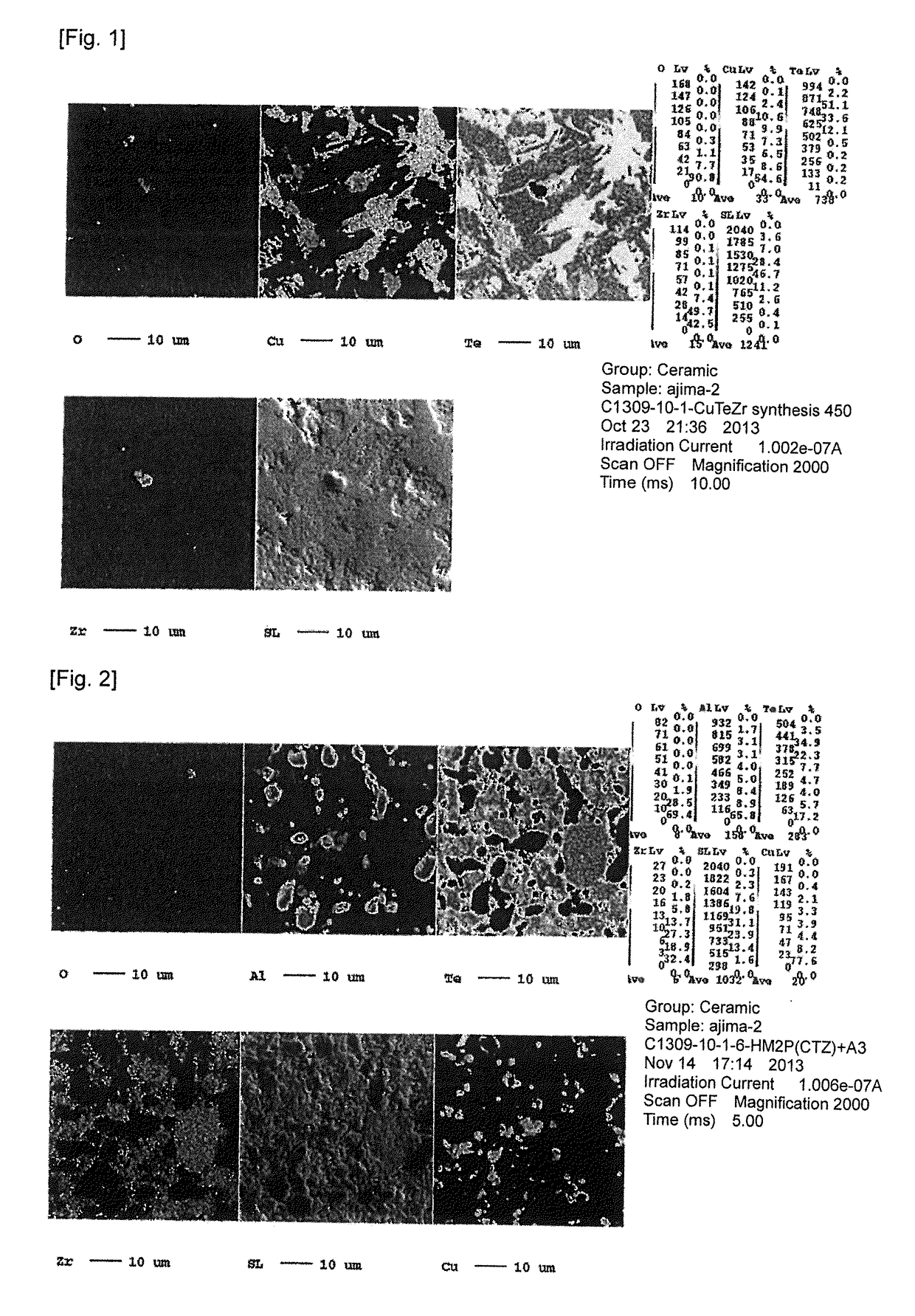
[0032]A Cu raw material with a purity of 4N and a Te raw material with a purity of 5N were weighed out to give a composition of Cu:Te=30:70 (at %). A Cu wire rod and a Te shot sized for a synthesis ampule were selected as raw materials. Then, the raw materials were charged into a high-purity quartz ampule and vacuum-sealed to prevent oxidation and contamination from the environment during dissolution. An ampule with an inner diameter of 80 mm and a length of 200 mm was selected and used so as to obtain a homogeneous temperature distribution and a uniformly mixed molten metal. Then, dissolution was performed to obtain an alloy. The temperature was maintained at 1000° C. for 4 hours to ensure that Cu and Te are thoroughly reacted and dissolved. During this process, a molten metal was allowed to oscillate at a frequency of 30 Hz for homogenization. After dissolution was completed, the content was cooled slowly to room temperature in the furnace to produce a cast ingot. A highly pure Cu...

example 2

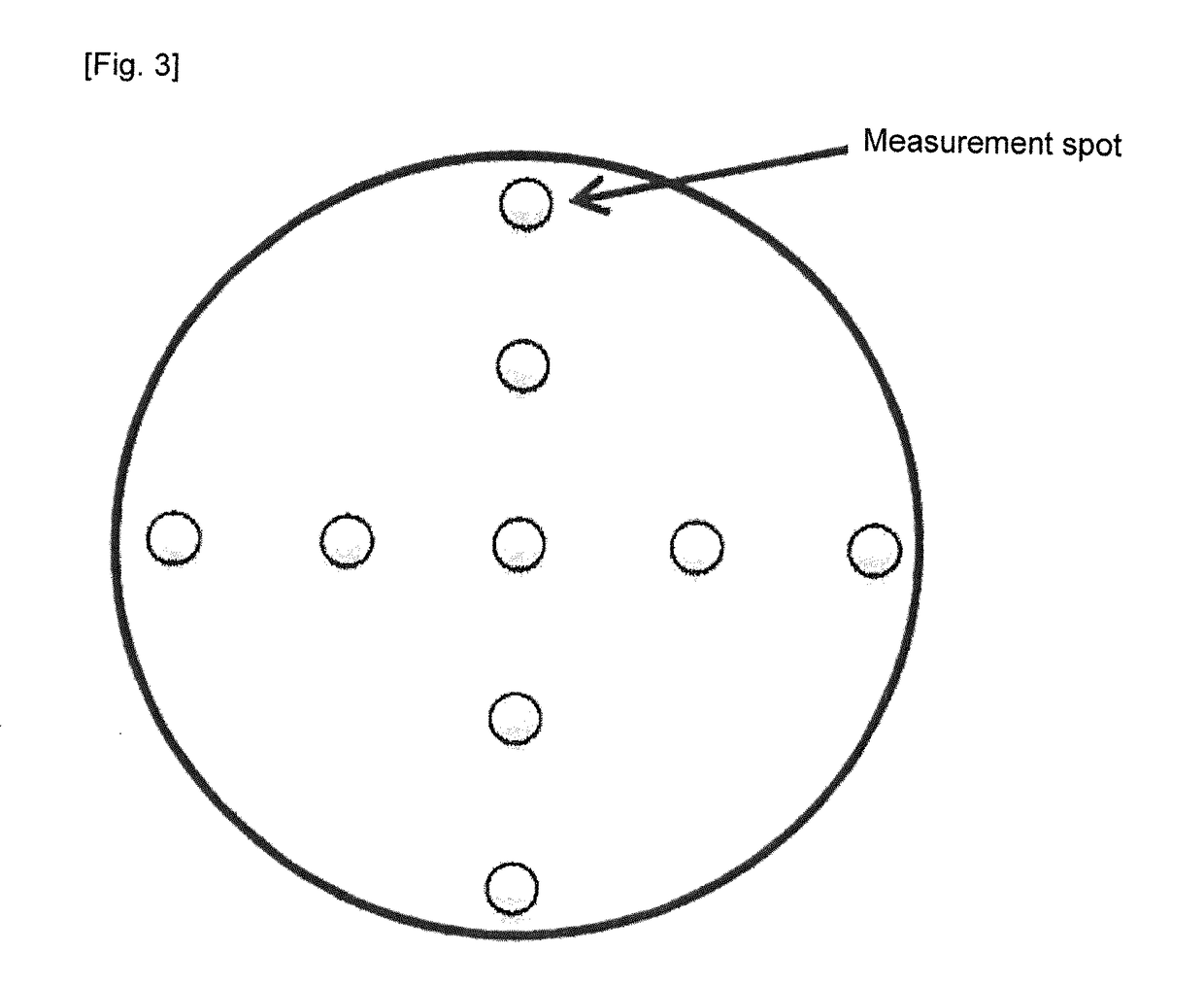
[0037]A sintered compact was produced under similar conditions as in Example 1 except that the temperature (maximum) when sintering a mixture of a CuTe powder and a Zr powder was changed to 500° C. (liquid phase reaction) from 400° C. An Al—Te—Cu—Zr alloy sintered compact with a purity of 3N or more, an oxygen concentration of 2900 wt. ppm, a relative density of 93% and a mean grain size of 9 μm was obtained in a way as described above. Observation showed that the sintered compact had a structure comprising an Al phase, a CuAl phase, a TeZr phase and a Zr phase. Then, this sintered compact was machined to produce a sputtering target, with which sputtering was performed under similar conditions as in Example 1. Results showed that the number of particles (0.2 μm or more) was as extremely low as 18.

example 3

[0038]The CuTe powder with a grain size of 90 μm or less which was produced in Example 1 was further pulverized with a jet mill. The maximum grain size after pulverization was 5 μm, and the content of oxygen was 680 wt. ppm. Then, hydrogen reduction was performed under the same conditions as in Example 1 to obtain a low-oxygen powder with an oxygen concentration of 80 wt. ppm. The resulting CuTe powder with a maximum grain size of 5 μm and an oxygen concentration of 80 wt. ppm, an Al powder with a maximum grain size of 10 μm and an oxygen concentration of 5100 wt. ppm and a Zr powder with a maximum grain size of 10 μm and an oxygen concentration of 8000 wt. ppm were weighed out and mixed to give the same composition as in Example 1. The resulting raw material powder was charged into a graphite die with a diameter of 480 mm, and hot-pressed to produce a sintered compact. As in Example 1, the sintering conditions were such that the sintering temperature was 325° C., the pressing press...


PUM

PropertyMeasurementUnit
Grain sizeaaaaaaaaaa
Temperatureaaaaaaaaaa

Abstract

An Al—Te—Cu—Zr alloy sputtering target, comprising 20 at % to 40 at % of Te, 5 at % to 20 at % of Cu, 5 at % to 15 at % of Zr and the remainder of Al, wherein a Te phase, a Cu phase and a CuTe phase are not present in a structure of the target. An object of the present invention is to provide an Al—Te—Cu—Zr alloy sputtering target capable of effectively reducing particle generation, nodule formation and the like upon sputtering and further capable of reducing oxygen contained in the target.

Description

TECHNICAL FIELD[0001]The present invention relates to a sputtering target comprising an Al—Te—Cu—Zr alloy and a method of manufacturing thereof. In particular, the present invention relates to an Al—Te—Cu—Zr alloy sputtering target for forming a thin film comprising an Al—Te—Cu—Zr alloy as a variable resistance material, and a method of manufacturing thereof.BACKGROUND ART[0002]As variable resistance recording materials, thin films comprising Te—Al based materials and Te—Zr based materials have been used in recent years for recording information by taking advantage of resistance change. Thin films comprising such materials are commonly formed by a so-called physical vapor deposition method such as the vacuum deposition method and the sputtering method. In particular, the magnetron sputtering method is often used in view of operativity and stable film formation.[0003]A method of forming a thin film by the sputtering method involves physically bombarding positive ions such as argon io...

Claims


Application Information

Patent Timeline
IPC IPC(8): C23C14/34C22C28/00C22C1/02B22F9/22B22D7/00B22F9/04B22F3/14C23C14/14C22C1/04
CPCC23C14/3414B22F2998/10C22C28/00C22C1/02C22C1/04B22D7/005B22F9/04B22F3/14B22F9/22B22F2201/10B22F2201/20B22F2201/013B22F2304/10B22F2304/058B22F2301/10B22F2301/205B22F2301/052C23C14/14C22C21/00C22C30/02G11B9/04H10N70/20H10N70/026H10N70/8828H01J37/3426
Inventor KOIDO, YOSHIMASA
Owner JX NIPPON MINING& METALS CORP
Why Eureka
Try Eureka