Mechanical flow joining of high melting temperature materials

a high melting temperature material and mechanical flow technology, applied in the direction of manufacturing tools, non-electric welding apparatus, transportation and packaging, etc., can solve the problems of brittleness of steel and other ferrous alloys, inability to fusion join, and inability to meet the requirements of fusion welding methods

Inactive Publication Date: 2017-07-13
MAZAK CORP
View PDF32 Cites 18 Cited by
  • Summary
  • Abstract
  • Description
  • Claims
  • Application Information

AI Technical Summary

Benefits of technology

[0021]The present disclosure is a system and method for securely join together a high melting temperature material and a backing substrate or plate using a mechanical connection.

Problems solved by technology

Force is exerted to urge the pin and the workpieces together and frictional heating caused by the interaction between the pin, shoulder and the workpieces results in plasticization of the material on either side of the joint.
However, fusion joining methods may not be practical because of potential thermal damage to the parts, distortion that prevents fit up with mating parts, solidification defects, safety, cost or simply that the materials being joined cannot be fusion joined due to the physical properties of the materials.
Mining of coal and minerals may require equipment that is continually exposed to hard rocks, abrasive minerals and random materials encountered during the mining operation.
The sintering process may give tungsten carbide its high hardness but may also leave it brittle compared to steel and other ferrous alloys.
Because tungsten carbide is brittle, sharp corners should not be designed or integrated into the design of the carbide component.
Sharp corners may be stress raisers and may create cracking during the sintering process or during subsequent usage in an application.
As a result, it may be difficult to include certain features into the design of the carbide component such as threads to hold bolts and other conventional features that function as locking mechanisms because they may have sharp corners.
Accordingly, it may be difficult to find a method to secure tungsten carbide components to equipment or to a surface that is exposed to the high loads that may be generated during mining and excavation operations.
One of the aspects with the design shown in FIG. 2 is that a tungsten carbide plate that is large enough to be used as a wear resistant plate may be a non-weldable material and may crack if any weld were attempted.
As for attaching the tungsten carbide plate 30 to the steel weldable work piece 32 using adhesive, applications of using the assembly may generate substantial heat from frictional wear which may cause the adhesive to decompose and delaminate the tungsten carbide from the steel weldable work piece substrate.
Other aspects of using an adhesive may include, but should not be considered as limited to, poor performance in very cold conditions, premature failure due to low strength or brittle failure, poor chemical resistance to acidic compounds, and the mechanical strength of adhesives is inherently very low and high shear forces generated by rock and debris may pull the tungsten carbide from the substrate during equipment operation.
Another known joining method is brazing, which also has limitations.

Method used


Image

  • Mechanical flow joining of high melting temperature materials
  • Mechanical flow joining of high melting temperature materials
  • Mechanical flow joining of high melting temperature materials

Examples


first embodiment

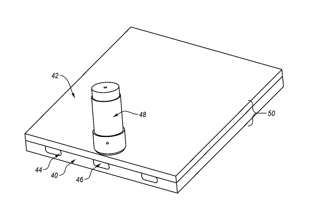
[0062]FIG. 5 shows a perspective view of the non-weldable work piece 40 with inserts 46 disposed in the grooves 44. In this first embodiment the inserts are in the shape of a bar, may be made of steel, and may be large enough that the inserts 46 cannot be pulled from the grooves 44 through the dovetailed opening in a direction that is perpendicular to a plane of the non-weldable work piece 40.

[0063]The material selected for the inserts 46 may be selected from but should not be considered as limited to the following materials including steel, stainless steel, aluminum, high nickel alloys such as Inconel or any other material that is capable of being friction stir welded.

[0064]In some embodiments, the inserts 46 may be made of a plurality of different materials. These different materials may be selected for a particular property that may be obtained from the combination. As an example, such materials may include but should not be considered as limited to a braze material, a corrosion ...

third embodiment

[0083]FIGS. 14, 15, and 16 are of the present disclosure where the objects forming a friction-stir joined assembly are tubulars such as pipes. FIG. 14 is three views of a high melting temperature material tubular object 80. The high melting temperature material tubular object 80 is shown in perspective, from an end relative to a long axis, and perpendicular to the axis. The high melting temperature material tubular object 80 includes grooves 86 disposed around a circumference.

[0084]FIG. 15 is three views of a tubular object 82 that may form a weldable work piece for the tubular object 80. The weldable work piece tubular object 82 is shown in perspective, from an end relative to a long axis, and perpendicular to the axis. The weldable work piece tubular object 82 is large enough so that the OD of the high melting temperature material tubular object 80 fits inside the ID of the weldable work piece tubular object 82. The weldable work piece tubular object 82 may form a tight fit around...


PUM

PropertyMeasurementUnit
thermally stableaaaaaaaaaa
shapeaaaaaaaaaa
melting temperatureaaaaaaaaaa

Abstract

A system and method for securely joining a high melting temperature material and a backing substrate using a mechanical connection includes a backing substrate integrally formed with a material positioned inside a dovetail recess in the high melting temperature material, mechanically fixing the backing substrate to the high melting temperature material without fusion or bonding of the microstructure.

Description

CROSS-REFERENCE TO RELATED APPLICATIONS[0001]This application claims priority to and the benefit of U.S. Provisional Patent Application No. 62 / 026,166, filed Jul. 10, 2014, the disclosure of which is incorporated herein by reference in its entirety.BACKGROUND[0002]Friction stir joining is a technology that has been developed for welding metals and metal alloys. Friction stir welding is generally a solid state process that has been researched, developed, and commercialized over the past 20 years. Solid state processing is defined herein as a temporary transformation into a plasticized state that may not include a liquid phase. However, it is noted that some embodiments allow one or more elements to pass through a liquid phase.[0003]Friction stir joining began with the joining of aluminum materials because friction stir joining tools could be made from tool steel and adequately handle the loads and temperatures that may be needed to join aluminum. Friction stir joining has continued t...

Claims


Application Information

Patent Timeline
Patent Type & Authority Applications(United States)
IPC IPC(8): B23K11/00B23K20/22B23K20/12
CPCB23K11/0053B23K20/1265B23K20/128B23K20/22E21F13/061B23K2203/10B23K2203/26B23K2203/18B23K2203/05B23K20/127B23K2103/05B23K2103/10B23K2103/18B23K2103/26
Inventor STEEL, RUSSELL J.FLECK, RODNEY DALETUCKER, CHRISTOPHER ARTHURPACKER, SCOTT M.ROSAL, DAVIDCANAVAN, JOHN T.KLINGINSMITH, MICHAEL D.
Owner MAZAK CORP
Why Eureka
Try Eureka