
Method and Apparatus for High Contrast Imaging

a high contrast imaging and high contrast technology, applied in the field of high contrast imaging, can solve the problems of low image contrast, difficulty in high contrast imaging, loss of scene fidelity, etc., and achieve the highest possible contrast, increase image fidelity, and enhance image contrast

Inactive Publication Date: 2017-08-17
OMNITEK PARTNERS LLC
View PDF4 Cites 3 Cited by
  • Summary
  • Abstract
  • Description
  • Claims
  • Application Information

AI Technical Summary

Benefits of technology

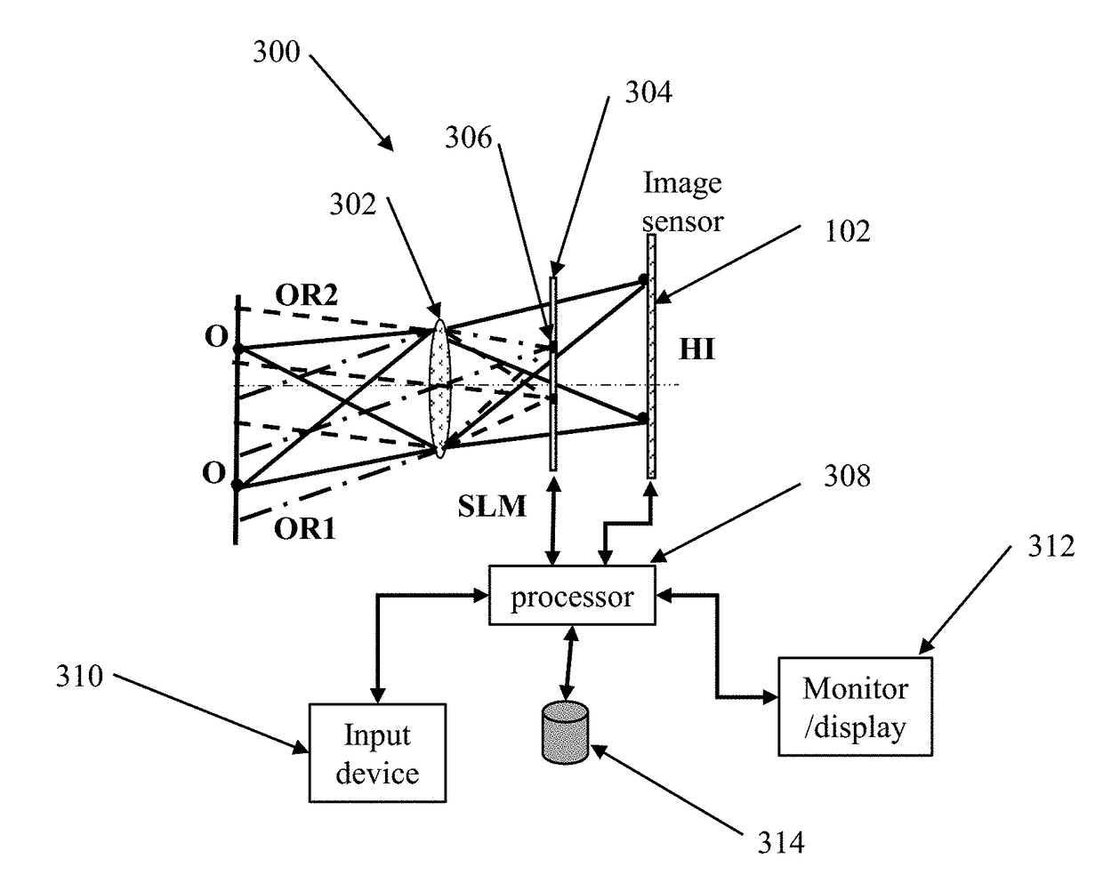
The patent text describes a method and device for improving the contrast of images captured using an optical system. The technique involves using spatial light modulators to control the brightness of the image at different locations on the image plane. This results in a higher fidelity image that can be viewed under both white light and monochromatic light. The method can be incorporated into existing endoscopic systems or standalone high contrast imaging systems and offers a dynamic real-time tool for clinicians to observe organs and tissue with the highest possible contrast. This method can also be used with pre-determined aperture stops for imaging modalities that are not expected to change. The technical effects of this patent include improved image quality and the ability to observe objects against a very bright background.

Problems solved by technology

High contrast imaging, in the presence of a bright background, is a challenging problem encountered in diverse applications ranging from the daily chore of driving into a sun-drenched scene to in vivo use of biomedical imaging in various types of keyhole surgeries, to low coherence interference microscopy to direct imaging of exoplanets in the back drop of star-to-planet brightness.
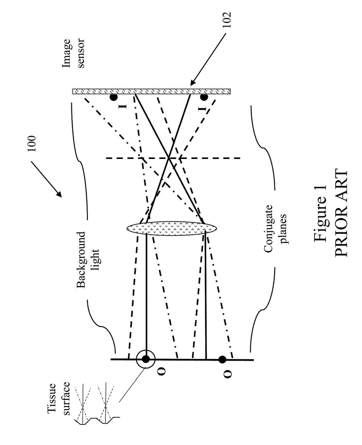
Imaging in the presence of bright sources saturates the vision system, resulting in loss of scene fidelity, corresponding to low image contrast and reduced resolution.
The problem is exacerbated in retro-reflective imaging systems where the light source(s) illuminating the object are unavoidably strong, typically masking the object features.
Furthermore, the strength and direction of the background signal may vary over the entire object surface and may also be time dependent.
With respect to the current focus on biomedical imaging, low contrast of in vivo images is particularly acute and leads to unacceptably low confidence levels for real-time diagnosis of diseased tissue based on direct observation.
Invariably, the patient is subjected to undergo biopsy, with a follow up visit, adding to health care cost, in addition to patient anxiety.
In keyhole or other surgical procedures based on indirect observation via an image bundle, lack of high contrast images causes over estimation of excision margins resulting in unnecessary loss of healthy tissue.
Despite advances in precision optics, and in imaging sensors, the fact remains that the optical imaging front end, basically primitive and passive, has gone through evolutionary changes over the last century, but nothing extraordinary.
Further, it should be noted that, no amount of digital signal processing can recover object detail lost due to low fidelity imaging, as a result of both detector saturation and low resolution imaging optics.
Conventional analytical techniques, based on the spatial frequency response, are inadequate.
However, as discussed above, such approaches are deficient and not able to recover the original object distribution.
Contemporary techniques, such as dark field imaging, reduce the amount of incident light entering the imaging optics, but do not improve the contrast as both background and object intensity are proportionally reduced.
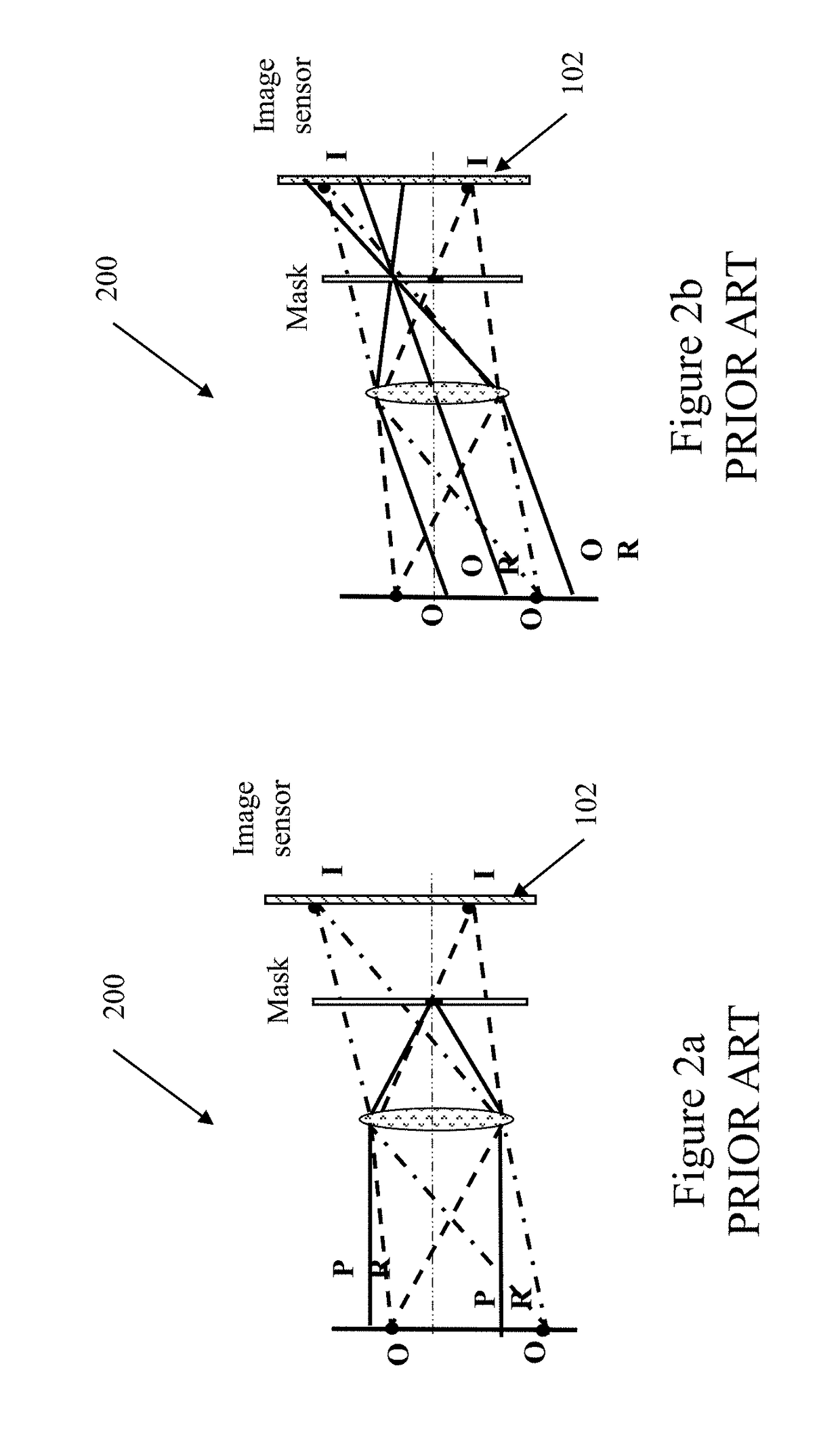
However, FIG. 2B illustrates the shortcomings of a fixed Fourier plane mask technique, which is ineffective at removing contributions arising from oblique rays (OR).
Thus, significant image contrast enhancements are precluded from being realized for practical systems falling outside the artificially imposed limitations of linearity (paraxial).

Method used


Image

  • Method and Apparatus for High Contrast Imaging
  • Method and Apparatus for High Contrast Imaging
  • Method and Apparatus for High Contrast Imaging

Examples


Embodiment Construction

[0029]It is understood that imaging can be performed at any suitable frequency and with the appropriate devices. Here for convenience, Applicants refer to the optical imaging system, that uses the visible and near infra-red spectral regions of the electromagnetic spectrum. Any arbitrary object is visible to the imaging system due to any number of physical attributes, such as, reflectivity, scattering or differential phase. The strength of the light intensity originating from the object and that originating from non-object features, are both dependent on the strength of the incident illumination. The goal of any imaging system is to capture as much of the light from the object features while minimizing the background light from entering the imaging system. In practice, it is not possible to reduce one without the other, resulting in poor object visibility due to the bright background. Contrast of the recorded image is further degraded due to the finite resolution of the image detecti...


PUM


Abstract

An apparatus for improving contrast in an image captured by an imaging sensor. The apparatus including: an objective optical system positioned in an optical path of illumination light on an object; an image sensor positioned in the optical path such that light from the objective optical system is incident on the image sensor; a device having a variable transparency positioned at a focal plane of the objective optical system; and a processor configured to: detect a bright spot on the image sensor; and control the device to change a transparency of a portion of the device corresponding to the detected bright spot.

Description

CROSS-REFERENCE TO RELATED APPLICATION[0001]This application claims the benefit to earlier filed U.S. Provisional Application No. 62 / 233,988 filed on Sep. 28, 2015, the entire contents of which is incorporated herein by reference.BACKGROUND OF THE INVENTION[0002]1. Field of the Invention[0003]The present invention relates generally to methods and devices for enhancing image contrast in the presence of bright background, and more particularly to image contrast enhancing methods and devices for the entire range of endoscopy, confocal endomicroscopy, and other similar devices used for imaging bright field objects, such as, human tissue, highly reflective semiconductor elements on wafers or MEM structures or the like.[0004]2. Prior Art[0005]High contrast imaging, in the presence of a bright background, is a challenging problem encountered in diverse applications ranging from the daily chore of driving into a sun-drenched scene to in vivo use of biomedical imaging in various types of key...

Claims


Application Information

Patent Timeline
IPC IPC(8): H04N5/238G02F1/01G03B7/08H04N5/232H04N5/235H04N5/225
CPCH04N5/238H04N5/2351H04N5/2256G02F2203/12H04N5/23293H04N5/2258G02F1/0126G03B7/08G03B9/08G03B19/02H04N23/63H04N23/75H04N23/45H04N23/56H04N23/71
Inventor DHADWAL, HARBANSRASTEGAR, JAHANGIR S.FENG, DAKE
Owner OMNITEK PARTNERS LLC
Learn More