

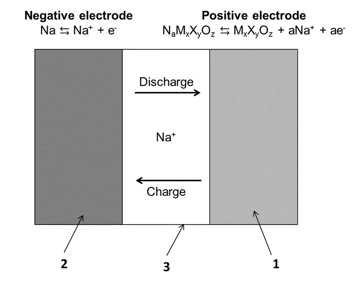
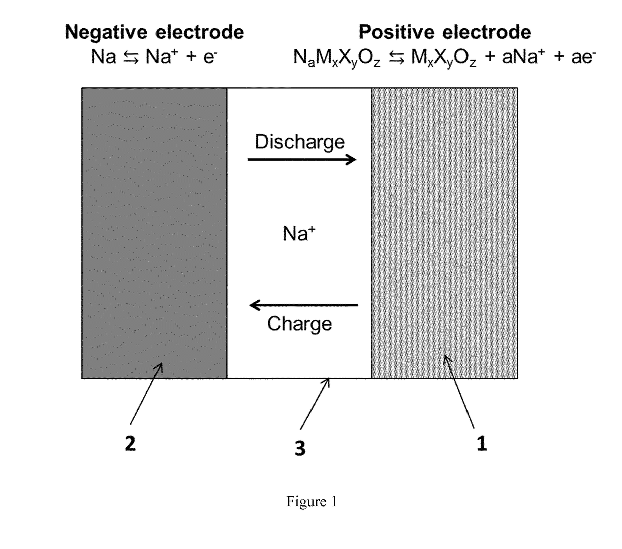
Sodium ceramic electrolyte battery
a sodium ceramic and electrolyte battery technology, applied in the field of secondary batteries, can solve the problems of zebra batteries from penetrating a broad market, electrical short circuit, and cost, and achieve the effect of low cos
- Summary
- Abstract
- Description
- Claims
- Application Information
AI Technical Summary
Benefits of technology
Problems solved by technology
Method used
Image

Examples
example 1
n of the Adhesion Properties of the Na / β″-Al2O3 Interface
[0142]Different pressures were tested to evaluate the adhesion properties of the Na / β″″-Al2O3 interface below the melting point of Na (98° C.). In order to compare the effect of pressure, Na / β″-Al2O3 / Na symmetric systems were prepared and electrochemically tested. β″-Al2O3 discs with 1 cm diameter, 500 μm thickness, 98-99% density, and ˜1.6 mS / cm ionic conductivity were used to perform the following experiments. Above 10 kg / cm2 the interface showed good apparent adhesion and was electrochemically evaluated by sodium plating / stripping tests below the melting point of sodium (98° C.).
[0143]Na electrodes (metallic foil) of 4 mm diameter with 1 mm thickness were pressed on each side of the β″-Al2O3. Pressure between 10-1000 kg / cm2 on Na / β″-Al2O3 was applied to stick the Na electrodes on both sides of the β″-Al2O3 disc. Above such range the β″-Al2O3 disc was observed to break; below such range, the Na electrodes were not sticking t...
example 2
ramic Battery with and without Beta″-Alumina Solid Electrolyte with Planar Configuration Using Na[Fe0.4Ni0.3Ti0.3]O2 as the Positive Electrode and Operating at 55° C.
Fabrication of the Positive Electrode
[0146]Stoichiometric amounts of Na2CO3 (99.5% purity supplied by Sigma Aldrich), Fe2O3 (99% purity supplied by Alfa Aesar), NiO (Ni 78.5% purity supplied by Alfa Aesar) and TiO2 (99.9% purity supplied by Alfa Aesar) were ball milled at 300 rpm for 1 hour and the resulting powder was pressed into a pellet. The pellet was calcined in air at 900° C. for 16 hours and quenched in liquid N2 to thereby obtain Na[Fe0.4Ni0.3Ti0.3]O2. After quenching, the pellet was introduced and stored in an Ar filled glove box (2O) in order to avoid any moisture contamination.
[0147]Na[Fe0.4Ni0.3Ti0.3]O2 obtained above, carbon black (supplied by Timcal) and poly(vinylidene fluoride) (supplied by Alfa Aesar) diluted in N-methylpyrrolidone (supplied by Sigma Aldrich) were mixed at a mass ratio of 75:15:10 and ...
example 3
ramic Battery with and without β″-Al2O3 Solid Electrolyte with Planar Configuration Using Na2 / 3[Mg0.2Mn0.8]O2 as the Positive Electrode and Operating at 55° C.
[0158]For comparative purposes, in order to demonstrate that equivalent results are obtained with the proposed new system for different insertion cathode materials, cells with a different insertion cathode have been analyzed. Cells with and without β″-Al2O3 were tested, again showing unexpectedly low polarization losses even with the addition of a 0.5 mm thick solid electrolyte. In particular, a battery having P2-type Na2 / 3[Mg0.2Mn0.8]O2 as positive electrode and NaFSI:C3C1pyrr[FSI] with a molar ratio of 2:8 as catholyte showed fifth cycle charge / discharge capacity of about 150 mAh / g when tested in the coin cell configuration at 55° C. with and without β″-Al2O3 solid electrolyte.
Fabrication of the Positive Electrode
[0159]Stoichiometric amounts of Na2CO3 (99.5% purity fabricated by Sigma Aldrich), Mn2O3 (98% purity supplied by ...
PUM
| Property | Measurement | Unit |
|---|---|---|
| Pressure | aaaaa | aaaaa |
| Electrical conductor | aaaaa | aaaaa |
| Metallic bond | aaaaa | aaaaa |
Abstract
Description
Claims
Application Information