Devices and Methods For Optical Spatial Mode Control

a technology of optical spatial mode and optical fiber, applied in non-linear optics, instruments, optical elements, etc., can solve the problems of significant limitations on the scaling of the modal area of an individual optical fiber, the inability to bend or curl the fiber arbitrarily, and the significant limitations of the fiber coiling method. achieve the effect of reducing size and weight, reducing the size and weight of the fiber, and reducing the size and weigh

Active Publication Date: 2017-10-19
MASSACHUSETTS INST OF TECH
View PDF9 Cites 40 Cited by
  • Summary
  • Abstract
  • Description
  • Claims
  • Application Information

AI Technical Summary

Benefits of technology

[0008]Advantages of using an all fiber-based system or other waveguide-based system can include greater robustness, greater output power, lower size and weight, and greater efficiency.
[0040]Controlling may include adjusting the BPP or beam intensity profile dynamically during a cutting, welding, brazing, hole drilling, or other material processing operation applied to the material workpiece. Controlling can further include adjusting the one or more spatial modes to minimize a back reflection of the common light beam.
[0047]The modulation controller can be further configured to control the plurality of modulators to adjust a BPP or beam intensity profile dynamically during a cutting, welding, brazing, hole drilling, or other material processing operation applied to the material workpiece. The modulation controller can be further configured to adjust the plurality of modulators to minimize a back reflection of the common light beam.
[0054]Controlling can further include: setting a power distribution of the common light beam for use of the common light beam at different work cells at different times; adjusting a beam product parameter (BPP) or beam intensity profile to optimize processing of the material workpiece, selectively, with respect to a material type or material thickness of the material workpiece or with respect to a relative motion between the material workpiece and one or more delivery optics used to deliver the common light beam to the material workpiece; adjusting a BPP or beam intensity profile dynamically during a cutting, welding, brazing, hole drilling, or other material processing operation applied to the material workpiece; or adjusting the one or more spatial modes to minimize a back reflection of the common light beam.

Problems solved by technology

Transverse mode (spatial mode) instability (TMI) (sometimes referred to as multimode instability, MMI) still imposes significant limitations on the scaling of modal area of an individual optical fiber, such as a fiber amplifier.
However, significant limitations have been observed with fiber coiling methods due to thermally induced nonlinearities that drive modal power coupling within the fiber, despite the relatively large higher-order mode losses that can be achieved.
Moreover, fibers cannot be bent or coiled arbitrarily due to issues of mode distortion, shrinking, and bend loss.
The larger the fiber core, the more critical these issues can become.
Furthermore, free-space-based methods of coherent beam combination (CBC) have significant limitations because of system size, complexity, and alignment tolerances.
Spatial light modulators, for example, tend to have power handling limitations and are generally less efficient and robust due to Fresnel losses and mode mismatch incurred using free-space optics.
In particular, it is difficult to achieve and maintain proper mode matching due to the spatial alignment tolerances in these types of free-space optical combiners.

Method used


Image

  • Devices and Methods For Optical Spatial Mode Control
  • Devices and Methods For Optical Spatial Mode Control
  • Devices and Methods For Optical Spatial Mode Control

Examples


Embodiment Construction

[0124]A description of example embodiments of the invention follows.

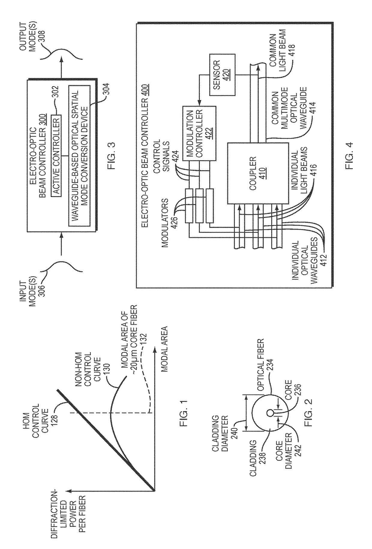
[0125]FIG. 1 is a graph that illustrates the effects of higher-order modes (HOMs) on the diffraction-limited power that can be achieved per optical fiber as modal area increases. In particular, if HOMs are eliminated, then the diffraction-limited power per fiber increases linearly with the fibers modal area, as illustrated in the linear curve 128. However, in the presence of transverse mode instability, where HOMs are not controlled, the diffraction-limited power per optical fiber first increases with modal area, then actually decreases as modal area continues to increase, as illustrated by a nonlinear curve 130 in FIG. 1. A maximum in this curve occurs around a modal area 132 of an optical fiber having a core of approximately 20 μm in diameter. Thus, power in an optical fiber is limited by nonlinearities. Some of these nonlinearities can include stimulated Brillouin scattering (SBS), stimulated Raman scattering (SR...


PUM

PropertyMeasurementUnit
diameteraaaaaaaaaa
diameteraaaaaaaaaa
diameteraaaaaaaaaa

Abstract

An electro-optic beam controller, material processing apparatus, or optical amplifier, and corresponding methods, can include an actively controlled, waveguide-based, optical spatial mode conversion device. The conversion device can include a coupler, which can be a photonic lantern, configured to combine light beams into a common light beam; a sensor configured to measure at least one characteristic of the common light beam; and a controller configured to modulate optical parameters of the individual, respective light beams to set one or more spatial modes of the common light beam. Actively controlled and modulated devices can be used to maintain a stable, diffraction-limited beam for use in an amplification, communications, imaging, laser radar, switching, or laser material processing system. Embodiments can also be used to maintain a fundamental or other spatial mode in an optical fiber even while scaling to kilowatt power.

Description

RELATED APPLICATION[0001]This application claims the benefit of U.S. Provisional Application No. 62 / 291,007, filed on Feb. 4, 2016. The entire teachings of the above Application are incorporated herein by reference.GOVERNMENT SUPPORT[0002]This invention was made with government support under Contract # FA8721-05-C-0002 from The United States Airforce. The government has certain rights in the invention.BACKGROUND[0003]Adaptive optical correction is prevalent in a variety of optical systems. As a beam propagates through optical disturbances, the wavefront of the beam degrades. Examples of optical disturbances include propagation through turbulent media including atmospheric or biological tissue, thermal lensing in optical glasses, and reflection from non-flat surfaces. Adaptive optical correction typically involves using a free-space optic, such as a deformable mirror or spatial light modulator, to pre-distort the beam such that the desired beam is achieved after propagating through t...

Claims


Application Information

Patent Timeline
Patent Type & Authority Applications(United States)
IPC IPC(8): G02F1/01H01S3/00G02F1/29
CPCG02F1/0115G02F1/29H01S3/005G02F2201/58G02F2203/24G02F2201/02G02F2201/05G02F1/0121G02B6/2804G02B6/2821G02B6/2826G02B6/2856
Inventor MONTOYA, JUANRIPIN, DANIELALESHIRE, CHRISTOPHERMARTZ, DALEREEVES-HALL, PETER COLIN
Owner MASSACHUSETTS INST OF TECH
Why Eureka
Try Eureka