Turbine shroud with abradable layer having dimpled forward zone

a turbine engine and abradable layer technology, applied in the direction of machines/engines, climate sustainability, foundry moulds, etc., can solve the problems of local variations in the blade tip gap, reducing the operational reducing the efficiency of the turbine engine, so as to enhance the porosity and abradability, and enhance the effect of hot working gas erosion resistan

Active Publication Date: 2017-12-28
SIEMENS ENERGY GLOBAL GMBH & CO KG
View PDF12 Cites 12 Cited by
  • Summary
  • Abstract
  • Description
  • Claims
  • Application Information

AI Technical Summary

Benefits of technology

[0016]More particularly, exemplary embodiments of the invention feature a turbine engine ring segment component, adapted for coupling to an interior circumference of a turbine casing in opposed orientation with a rotating turbine blade tip circumferential swept path. The blade tip has a rotational direction, a leading edge, a mid-chord cutoff point on its pressure side concave surface and a trailing edge. The component comprises a curved support surface adapted for coupling to a turbine casing inner circumference, with the support surface having upstream and downstream axial ends and a support surface curvature radius defined by a support surface central axis. An abradable substrate is coupled to the support surface, having a substrate surface facing the support surface central axis. The substrate surface defines a forward zone originating nearer the support surface upstream end and terminating axially between the support surface ends. The substrate also defines an aft zone originating at the adjoining forward zone termination and terminating axially nearer the support surface downstream end. The forward zone defines a plan form pattern of projection or indentation dimples facing the support surface central axis, with the dimples respectively having cross sectional profiles, for selectively varying the forward zone's hot working gas erosion resistance, porosity, and / or abradability. The aft zone defines a plan form pattern of grooves and vertically projecting ridges facing the support surface central axis, angularly oriented at a first forward angle transverse to the support surface central axis. The respective forward zone dimple pattern enhances higher hot working gas erosion resistance than in the aft zone; and the respective aft zone ridge and groove pattern enhances greater porosity and abradability than in the forward zone.
[0017]Other exemplary embodiments of the invention feature a turbine engine, comprising a turbine housing including a turbine casing interior circumference, and a rotor having blades rotatively mounted in the turbine housing along a turbine blade rotational axis. The blade distal tips sweep a blade tip circumferential swept path in the blade rotation direction, which swept path extends axially with respect to the turbine casing interior circumference. Each turbine blade has a leading edge, a mid-chord cutoff point on its pressure side concave surface and a trailing edge, oriented at a trailing edge angle relative to turbine blade rotational axis. The engine also includes a ring segment component having a curved support surface adapted for coupling to a turbine casing inner circumference. The support surface has upstream and downstream axial ends and a support surface curvature radius defined by a support surface central axis. An abradable substrate is coupled to the support surface, having a substrate surface facing the support surface central axis. The substrate surface defines a forward zone originating nearer the support surface upstream end and terminating axially between the support surface ends. The substrate surface defines an aft zone originating at the adjoining forward zone termination and terminating axially nearer the support surface downstream end. The forward zone defines a plan form pattern of projection or indentation dimples facing the support surface central axis, with the dimples respectively having cross sectional profiles, for selectively varying hot working gas erosion resistance, porosity, and / or abradability of the forward zone. The aft zone defines a plan form pattern of grooves and vertically projecting ridges facing the support surface central axis, angularly oriented at a first forward angle transverse to the support surface central axis and opposite corresponding turbine blade rotational direction. The forward zone dimple pattern enhances higher hot working gas erosion resistance than in the aft zone; and the aft zone ridge and groove pattern enhances greater porosity and abradability than in the forward zone.
[0018]Additional exemplary embodiments of the invention feature a method for enhancing operational service life of a turbine engine. The method is practiced by providing a turbine engine, having a turbine housing, including a turbine casing interior circumference, and a rotor having blades rotatively mounted in the turbine housing along a turbine blade rotational axis. Distal tips of the blades form a blade tip circumferential swept path in the blade rotation direction, the swept path extending axially with respect to the turbine casing interior circumference. Each turbine blade has a leading edge, a mid-chord cutoff point on its pressure side concave surface and a trailing edge, oriented at a trailing edge angle relative to turbine blade rotational axis. The provided turbine engine also has a ring segment component having a curved support surface, which is adapted for coupling to a turbine casing inner circumference. The support surface has upstream and downstream axial ends and a support surface curvature radius defined by a support surface central axis. An abradable substrate is coupled to the support surface, having a substrate surface facing the support surface central axis. The substrate surface defines a forward zone, originating nearer the support surface upstream end and terminating axially between the support surface ends. The substrate surface also defines an aft zone, originating at the adjoining forward zone termination and terminating axially nearer the support surface downstream end. A plan form pattern of projection or indentation dimples facing the support surface central axis is formed in the forward zone, with the dimples respectively having cross sectional profiles. In the aft zone, a plan form pattern of grooves and vertically projecting ridges is formed. The rooves and ridges face the support surface central axis, and are angularly oriented at a first forward angle transverse to the support surface central axis and opposite corresponding turbine blade rotational direction, for selectively varying hot working gas erosion resistance, porosity, and / or abradability in the aft zone. The respective forward zone dimple pattern enhances higher hot working gas erosion resistance than in the aft zone; and the respective aft zone ridge and groove pattern enhances greater porosity and abradability than in the forward zone.

Problems solved by technology

Similarly, small mechanical alignment variances during engine assembly can cause local variations in the blade tip gap.
The excessive blade gap GW distortion increases blade tip leakage L, diverting hot combustion gas away from the turbine blade 92 airfoil, reducing the turbine engine's efficiency.
Past abradable component, designs have required stark compromises between blade tips wear resulting from contact between the blade tip and the abradable surface and blade tip leakage that reduces turbine engine operational efficiency.
Aggressive ramp-up rates exacerbated potential higher incursion of blade tips into ring segment abradable coating, resulting from quicker thermal and mechanical growth and higher distortion and greater mismatch in growth rates between rotating and stationary components.
Whether in standard or fast start configuration, decreasing blade tip gap for engine efficiency optimization ultimately risked premature blade tip wear, opening the blade tip gap and ultimately decreasing longer-term engine performance efficiency during the engine operational cycle.
However, groove dimensions were inherently limited by the packing spacing and diameter of the spheres in order to prevent sphere breakage.

Method used


Image

  • Turbine shroud with abradable layer having dimpled forward zone
  • Turbine shroud with abradable layer having dimpled forward zone
  • Turbine shroud with abradable layer having dimpled forward zone

Examples


embodiment 360

[0082]FIG. 25 shows an abradable component 360 having an inclined, symmetric sidewall rib, cross sectional profile abradable component with inclusion of dual level grooves 368A formed in the ridge tips 364 and 368B formed between the ridges 362 to the substrate surface 367. The upper grooves 368A form shallower depth DG lateral ridges that comprise the wear zone I while the remainder of the ridge 362 below the groove depth comprises the lower wear zone II. In this abradable component embodiment 360, the upper grooves 368A are oriented parallel to the ridge 362 longitudinal axis and are normal to the ridge tip 364 surface, but other groove orientations, profiles and depths may be employed to optimize airflow control and / or minimize blade tip wear.

[0083]In the abradable component 370 embodiment of FIG. 26, a plurality of upper grooves 378A are tilted fore-aft relative to the ridge tip 374 at angle γ, depth DGA and have parallel groove sidewalls. Upper wear zone I is established betwee...

embodiment 390

[0084]As shown in FIG. 28, upper grooves do not have to have parallel sidewalls and may be oriented at different angles relative to the ridge tip surface. In addition, upper grooves may be utilized in ridges having varied cross sectional profiles. The ridges of the abradable component embodiment 390 have symmetrical sidewalls that converge in a ridge tip. As in previously described embodiments having dual height grooves, the respective upper wear zones I are from the ridge tip to the bottom of the groove depth DG and the lower wears zones II are from the groove bottom to the substrate surface. In FIG. 28, the upper groove 398A is normal to the substrate surface (ε=90°) and the groove sidewalls diverge at angle Φ. For brevity, the remainder of the structural features and dimensions are labelled in FIG. 28, with the same conventions as the previously described abradable surface profile embodiments and has the same previously described functions, purposes, and relationships.

[0085]In FI...

embodiment 340

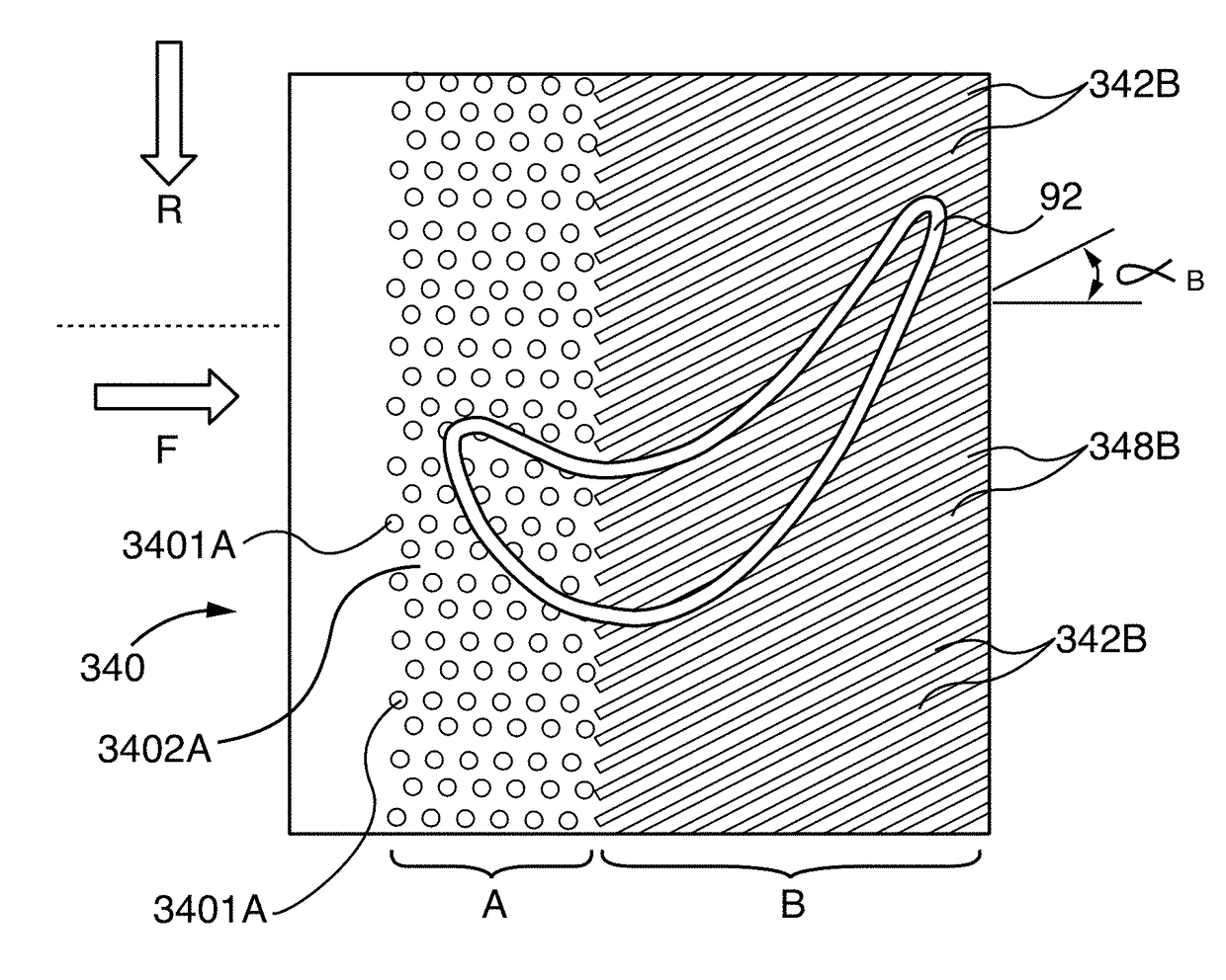
[0096]Notwithstanding the universally applicable forward zone A dimpled engineered surface feature of the abradable component embodiment 340 of FIG. 38, in some applications it is preferable or desirable to utilize hockey stick-like ridges and groove patterns in both zones that are tailored for the airflow characteristics of a specific blade airfoil profile. The Row 2 blade profile of FIGS. 41 and 42 differs from the Row 1 blade profile of FIGS. 39 and 40. The abradable component 480 plan form in FIG. 43 is tailored to match the Row 2 blade 920 airflow characteristics. The abradable component 480 has a non-inflected, bi-angle hockey stick plan form wherein the plan form line-segment pattern of the grooves and ridges in the forward and aft zones are both angled in the same direction opposite the blade 920 rotation direction R. The first or forward angle αA and second or aft angle αB are defined relative to the support surface axis, which is oriented parallel to the corresponding turb...


PUM

PropertyMeasurementUnit
trailing edge angleaaaaaaaaaa
heightaaaaaaaaaa
heightaaaaaaaaaa

Abstract

Turbine and compressor casing abradable components for turbine engines include abradable surfaces with a zonal system of forward (zone A) and rear or aft sections (zone B) surface features. The zone A surface profile comprises an array pattern of non-directional depression dimples, or upwardly projecting dimples, or both, in the abradable surface. The dimpled forward zone A surface features reduce surface solidity in a controlled manner, to help increase abradability during blade tip rubbing incidents, yet they provide sufficient material to resist incoming hot working fluid erosion of the abradable surface. In addition, the dimples provide generic forward section aerodynamic profiling to the abradable surface, compatible with different blade airfoil-camber profiles. The aft zone B surface features comprise an array pattern of ridges and grooves.

Description

PRIORITY CLAIM AND CROSS-REFERENCE TO RELATED APPLICATIONS[0001]This application claims priority under International Patent Application “TURBINE ABRADABLE LAYER WITH COMPOSITE NON INFLECTED BI ANGLE RIDGES AND GROOVES”, assigned Application No. PCT / US2015 / 016315, filed Feb. 18, 2015, which in turn claims priority under International Patent Application “COMPOSITE “HOCKEY STICK”-LIKE GROOVES ON TURBINE RING SEGMENT SURFACE”, assigned Application No. PCT / US2014 / 033785, filed Apr. 11, 2014, which in turn claims priority under U.S. patent application Ser. No. 14 / 188,992, filed Feb. 25, 2014, “TURBINE ABRADABLE LAYER WITH PROGRESSIVE WEAR ZONE TERRACED RIDGES”, now U.S. Pat. No. 8,939,707, issued Jan. 27, 2015, the entire contents of all of which are incorporated by reference herein. This application will be a continuation-in-part of the aforementioned U.S. patent application Ser. No. 14 / 188,992 in National Phase prosecution before the United States Patent and Trademark Office.[0002]This ...

Claims


Application Information

Patent Timeline
Patent Type & Authority Applications(United States)
IPC IPC(8): F01D11/12
CPCF01D11/122F05D2220/32F05D2230/00F05D2240/11F05D2250/60F01D5/18F01D5/186F01D5/288F01D9/02F01D11/08F01D11/12F05D2260/231F05D2300/6033C23C4/02C23C4/18C23C28/3215C23C28/3455C23C4/073F05D2250/12F05D2250/15F05D2250/182F05D2250/183F01D11/127F04D29/526F04D29/685F05D2230/30F05D2230/90F05D2250/184F05D2250/185F05D2250/23F05D2250/292F05D2250/294F05D2250/75F05D2260/202F05D2260/22141F05D2250/282F01D5/28B22C7/02B22C9/24B22D25/02B22D29/001F01D5/284Y02T50/60C23C28/00B32B3/30B32B5/26B32B2603/00B32B2262/105B32B15/14B32B2255/20B32B2255/02B32B2260/023B32B2260/04C04B35/80F01D5/187F01D9/023F01D25/12F05D2230/211F05D2300/175B28B11/048B28B19/0015F05D2230/31
Inventor THAM, KOK-MUNLEE, CHING-PANG
Owner SIEMENS ENERGY GLOBAL GMBH & CO KG
Why Eureka
Try Eureka