
All solid state lithium battery

a lithium battery, solid-state technology, applied in batteries, sustainable manufacturing/processing, cell components, etc., can solve the problems of low energy density, disadvantageous small capacity of batteries, and inability to efficiently intercalate and deintercalate lithium ions, etc., to achieve low energy density, small capacity, and large thickness

Inactive Publication Date: 2017-12-28
NGK INSULATORS LTD
View PDF0 Cites 18 Cited by
  • Summary
  • Abstract
  • Description
  • Claims
  • Application Information

AI Technical Summary

Benefits of technology

The patent text describes an all-solid-state lithium battery with a thin-film positive electrode layer. The thickness of the positive electrode layer is limited by the sputtering process, which results in low lithium conductivity and limited intercalation and deintercalation of lithium ions over the entire thickness of the layer. To address this issue, the inventors developed an oriented positive electrode plate with a high capacity and high energy density. The oriented positive electrode plate has a steeply decreased thickness at the end, which prevents short-circuiting between the substrate and the negative electrode layer. The use of a thin solid electrolyte layer between the positive electrode layer and the negative electrode layer further prevents short-circuiting and ensures efficient insulation. The orientation of the positive electrode plate also reduces the risk of cracking and peeling during battery operation. Overall, the invention provides an effective solution for preventing short-circuiting and improving the performance of all-solid-state lithium batteries.

Problems solved by technology

Unfortunately, the sputtering cannot form a positive electrode layer (which has a role as a reservoir of lithium ions) having a large thickness, hence, the battery disadvantageously has a small capacity and a low energy density.
This is because that the positive electrode layer formed by sputtering has low lithium conductivity and that a thick positive electrode precludes efficient intercalation and deintercalation of lithium ions over the entire thickness of the positive electrode layer.
For example, lithium present apart from the solid electrolyte of the thick positive electrode layer cannot be sufficiently deintercalated.
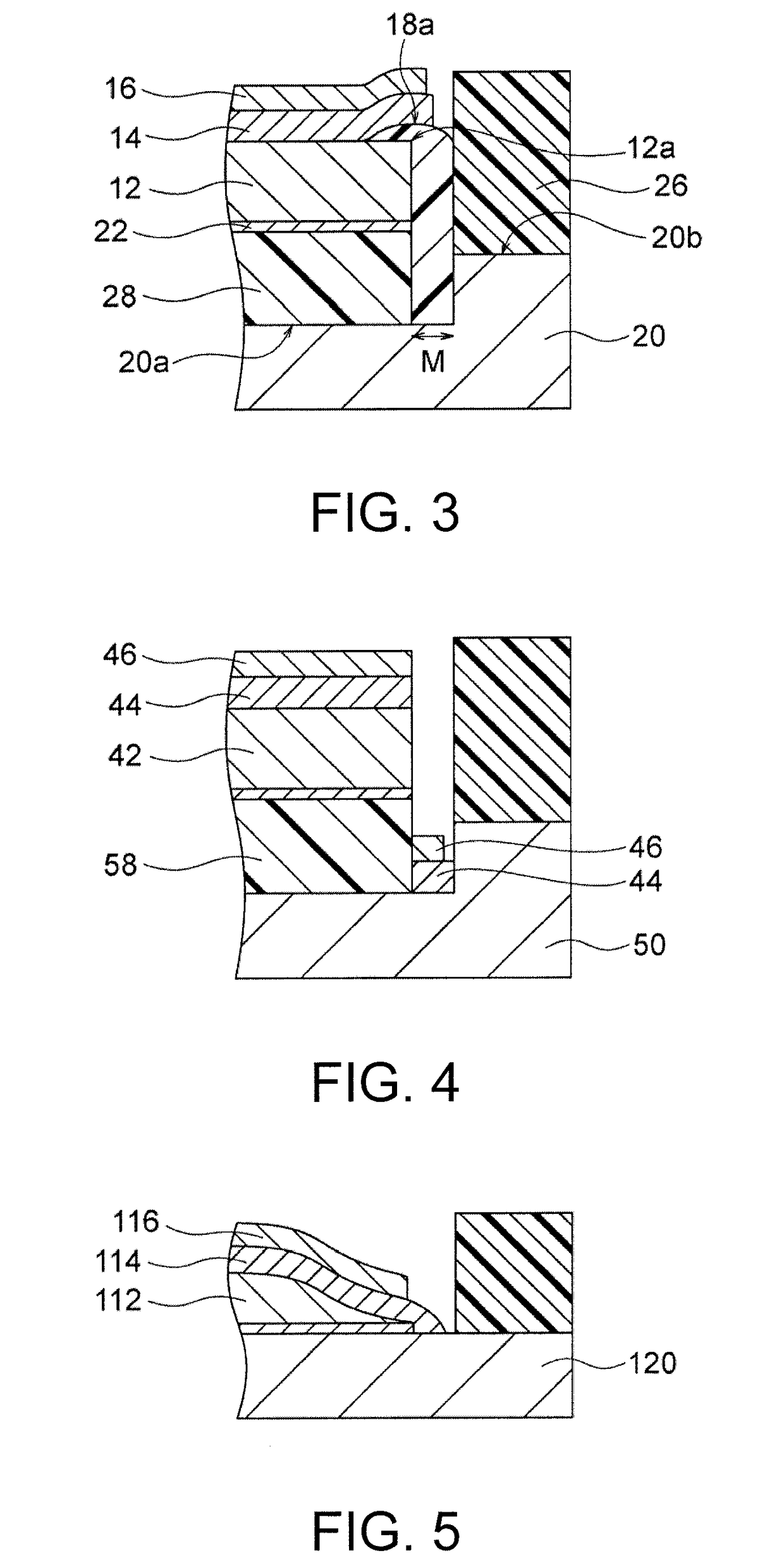
In such a case, the negative electrode layer 46 may adhere to the side surface at the end of the oriented positive electrode plate 42, leading to a risk of insufficient insulation at the end of the oriented positive electrode plate 42.
However, such a large thickness of the solid electrolyte layer may be undesirable in view of charge-discharge rate.
The oriented positive electrode plate has characteristics of expanding in the surface direction by deintercalation of lithium ions during a charging operation, leading to a risk of cracking of the oriented positive electrode plate and peeling at the interface between the oriented positive electrode plate and the solid electrolyte layer.
Such cracking and peeling deteriorate the performance.

Method used


Image

  • All solid state lithium battery
  • All solid state lithium battery
  • All solid state lithium battery

Examples


examples

[0087]The present invention will now be described more in detail with reference to the following examples.

examples 1 to 18

[0088]In each of Examples 1 to 18, an oriented positive electrode plate and an all-solid-state lithium battery were produced and the yield of the battery was evaluated as follows.

(1) Preparation of Oriented Positive Electrode Plate

(1a) Preparation of Green Sheet

[0089]Bi2O3 (volume-based D50 particle diameter: 0.3 μm, manufactured by Taiyo Koko Co., Ltd.) in an amount of 10 wt % was added to a Co3O4 raw material powder (volume-based D50 particle diameter: 0.3 μm, manufactured by Seido Chemical Industry Co., Ltd.) into a powder mixture. A mixture composed of 100 parts by weight of this powder mixture, 100 parts by weight of a dispersion medium (toluene:isopropanol=1:1), 10 parts by weight of a binder (polyvinyl butyral: Product No. BM-2, manufactured by Sekisui Chemical Co., Ltd.), 4 parts by weight of a plasticizer (DOP: di(2-ethylhexyl)phthalate, manufactured by Kurogane Kasei Co., Ltd.), and 2 parts by weight of a dispersant (Product Name: Leodol SP-O30, manufactured by Kao Corpora...

example 19

[0105]Another example of the production of an all-solid-state lithium battery will be described below.

(1) Production of oriented positive electrode plate

[0106]As in Examples 1 to 18, a lithium cobaltate oriented fired plate of LiCoO2 was prepared as an oriented positive electrode plate.

(2) Production of All-Solid-State Lithium Battery

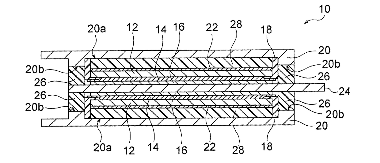
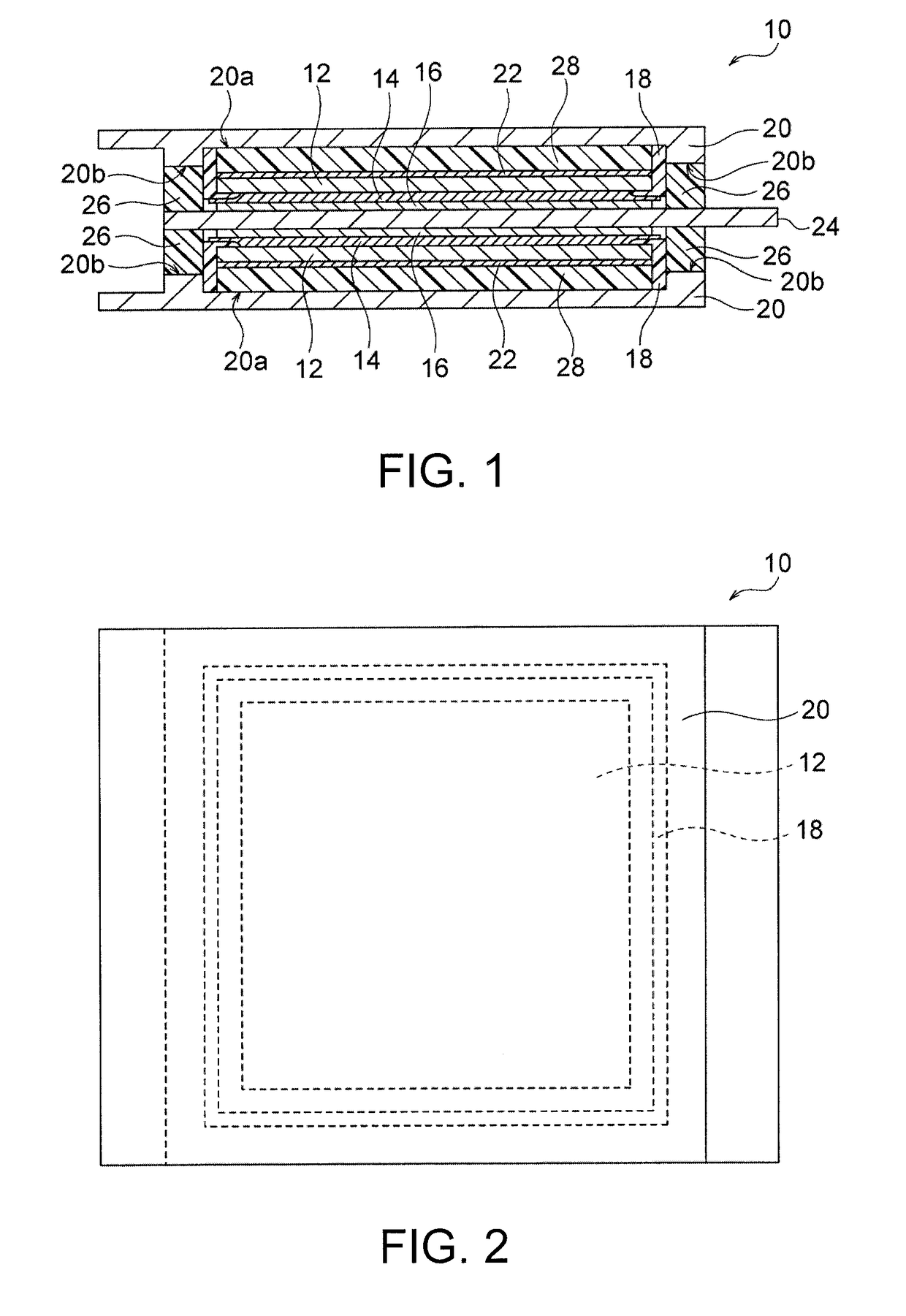
[0107]In an all-solid-state lithium battery having a structure as shown in FIG. 1, a lower half of the all-solid-state lithium battery, which corresponds to the unit cell under the negative electrode cladding, was produced as follows.

(2a) Production of Thin Metal Layer

[0108]An Au film having a thickness of 1000 angstrom was formed on one surface of a lithium cobaltate oriented positive electrode plate 12 by sputtering with an ion sputtering system JFC-1500 (manufactured by JEOL Ltd.) into a thin metal layer 22.

(2b) Production of End Insulator

[0109]An organic polymer and a filler shown in Table 1 were dispersed in a dimethyl ether solvent. The resulting ...


PUM


Abstract

Provided is an all-solid-state lithium battery including an oriented positive electrode plate composed of an oriented polycrystalline body made of lithium transition metal oxide grains, a solid electrolyte layer, a negative electrode layer, and an end insulator insulating and coating ends of the oriented positive electrode plate. The surface of the end insulator and the surface of the oriented positive electrode plate adjacent the solid electrolyte layer form one continuous surface no step exists. Alternatively, the height of the surface of the end insulator adjacent the solid electrolyte layer is lower than that of the surface of the oriented positive electrode plate adjacent the solid electrolyte layer to form a discontinuous surface with proviso that a step between the end insulator and the surface of the oriented positive electrode plate adjacent the solid electrolyte layer is smaller than the thickness of the solid electrolyte layer.

Description

CROSS-REFERENCE TO RELATED APPLICATIONS[0001]This application is a continuation application of PCT / JP2016 / 057652 filed Mar. 10, 2016, which claims priority to Japanese Patent Application No. 2015-062652 filed Mar. 25, 2015, the entire contents all of which are incorporated herein by reference.BACKGROUND OF THE INVENTION1. Field of the Invention[0002]The present invention relates to all-solid-state lithium batteries.2. Description of the Related Art[0003]The recent development of portable devices, such as personal computers and cellular phones, has been greatly expanding the demand for batteries as the power sources of the devices. Traditional batteries for such application contain liquid electrolytes (electrolytic solutions) containing flammable organic diluent solvents, as media for ion transfer. The battery containing such an electrolytic solution has a risk of the leakage of the electrolytic solution, ignition, explosion, or the like.[0004]To solve the problems, an all-solid-stat...

Claims


Application Information

Patent Timeline
IPC IPC(8): H01M2/34H01M10/0525H01M4/525H01M2/08H01M2/02H01M2/30H01M2/16H01M2/14H01M4/131H01M4/505H01M50/103H01M50/186H01M50/193H01M50/586H01M50/593
CPCH01M2/34H01M10/0525H01M2/1653H01M2/145H01M2/08H01M2220/30H01M4/131H01M4/525H01M4/505H01M2/30H01M2/0202H01M10/052H01M10/0562H01M10/0585H01M4/661H01M10/0436H01M2004/021H01M2300/0068Y02E60/10Y02P70/50H01M50/103H01M50/186H01M50/193H01M50/593H01M50/586
Inventor MAEDA, KAZUKIYOSHIDA, TOSHIHIROSHIMONO, MASAHIROSHIMOGAWA, NATSUMI
Owner NGK INSULATORS LTD
Learn More