Adaptive Stimulation System

Active Publication Date: 2018-01-04
GILSTAD DENNIS W +1
View PDF0 Cites 2 Cited by
  • Summary
  • Abstract
  • Description
  • Claims
  • Application Information

AI Technical Summary

Benefits of technology

The patent text discusses how fracturing can be optimized to increase the production of oil and gas from underground reservoirs. This is done by adjusting the fracing process to stimulate the geology in a way that reduces the time it takes for the oil and gas to flow back out of the well. The text also mentions the use of a special groove design that helps to stabilize the fracturing process. Overall, the patent text describes how to improve the efficiency of fracturing to increase oil and gas production.

Problems solved by technology

Such pumps are rated at peak pumped-fluid pressures in current practice up to about 22,000 psi, while simultaneously being weight-limited due to the carrying capacity of the trucks on which they are mounted.
Repeated application of dual valve-closure shocks with each pump cycle (i.e., one shock from the suction valve and another shock from the discharge valve) predisposes each check valve, and the pump as a whole, to vibration-induced (e.g., fatigue) damage.
Thus, cumulative valve-closure shocks significantly degrade frac pump reliability, proportional in part to the rigidity and weight of each check valve body.
And frac pumps with conventionally-rigid valves can suffer hundreds of these impulses per minute.
In conventional frac pumps, nearly all of the (relatively broad-spectrum) valve-generated vibration energy must be transmitted to proximate areas of the fluid end or pump housing because vibration energy cannot be efficiently dissipated in the (relatively rigid) valves themselves.
Based on extensive shock and vibration test data (see Harris) it can be expected to excite damaging resonances that predispose the housing to fatigue failures.
If, as expected, a natural vibration resonance frequency of the housing coincides with a frequency within the valve-closure vibration spectrum, fluid end vibration amplitude may be substantially increased and the corresponding vibration fatigue damage made much worse.
That is, spectra of the equipment vibration frequencies measured after application of test shocks can reveal structural resonance frequencies likely to cause trouble in a particular fluid end.
If vibration is not appropriately limited, fatigue cracks may grow to a point where fatigue crack size is no longer limited (i.e., the structure experiences catastrophic fracture).
Note that stronger housings are not necessarily better in such cases, since increasing the housing's yield strength causes a corresponding decrease in critical crack size (with consequent earlier progression to catastrophic fracture).
Substantially increased fluid end failure rates (due, e.g., to cracks near a suction valve seat deck) have been among the unfortunate, and unintended, consequences.
Important torsional-vibration failure modes suddenly became evident in the new six-cylinder engines, though they were neither anticipated nor understood at the time.
Whereas the earlier engines had been under-powered but relatively reliable, torsional crankshaft vibrations in the six-cylinder engines caused objectionable noise (“octaves of chatter from the quivering crankshaft”) and unexpected catastrophic failures (e.g., broken crankshafts).
The problem will be persistent because repeatedly-applied valve-closure energy impulses cannot be entirely eliminated in check-valve-based fluid end technology.

Method used


Image

  • Adaptive Stimulation System
  • Adaptive Stimulation System
  • Adaptive Stimulation System

Examples


embodiment 99

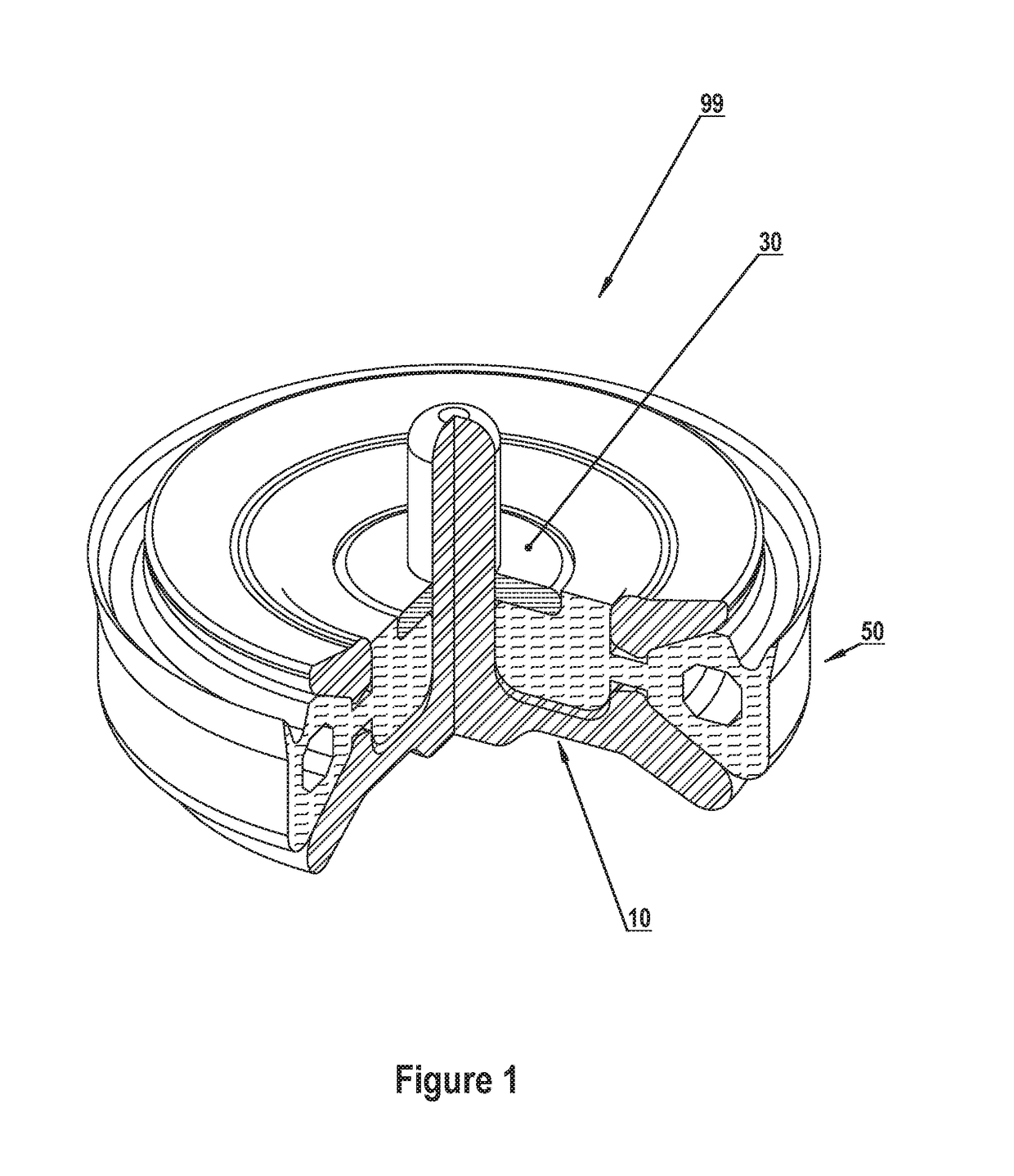
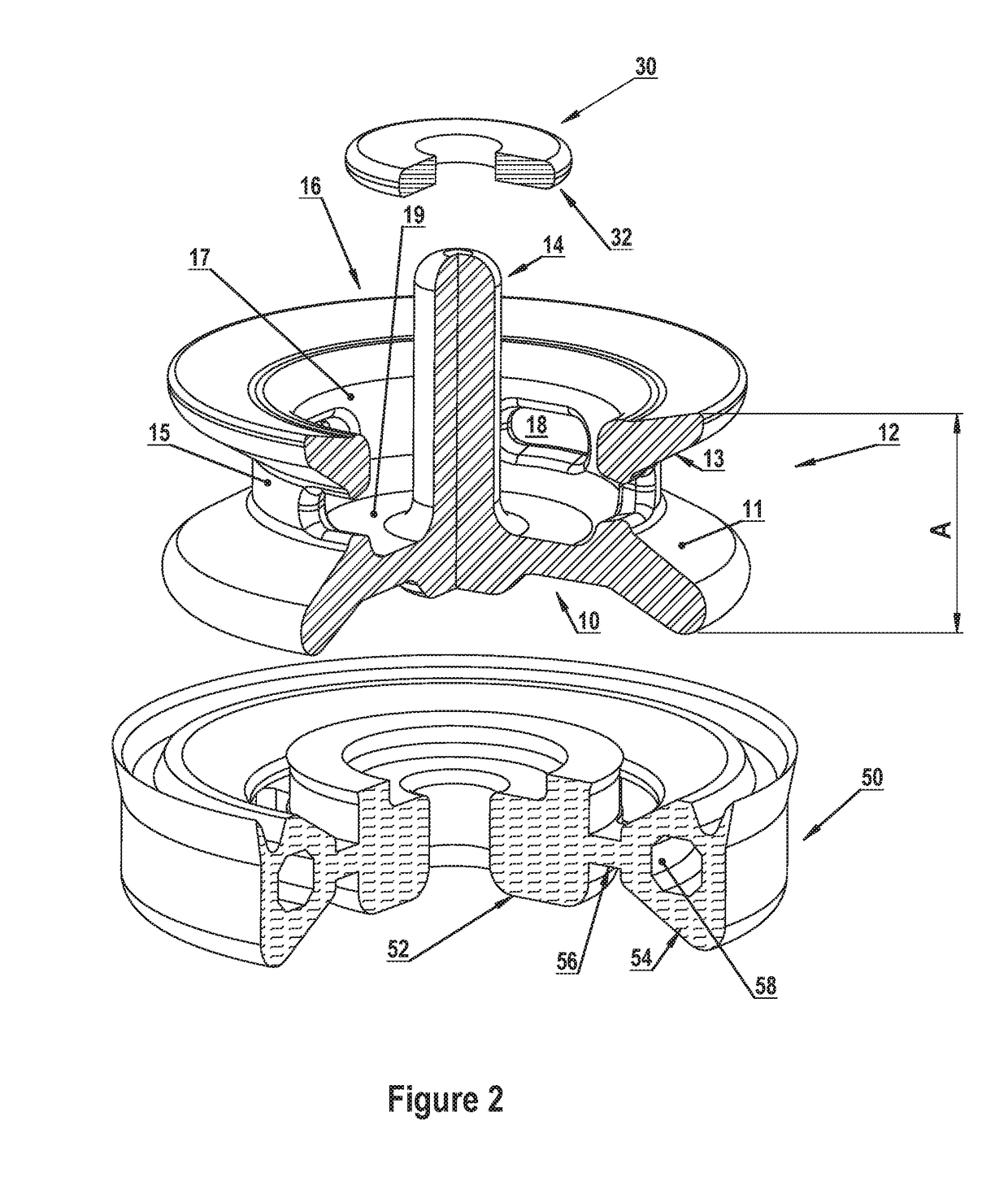
[0186]Referring to FIGS. 1 and 2 in greater detail, a tunable check valve assembly / tunable radial array embodiment 99 comprises viscoelastic body elements 50 which comprise, in turn, reservoir (central) element 52 coupled to groove (peripheral) element 54 via radial fenestration (tension) elements 56. Elements 52, 54 and 56 are disposed in (i.e., integrated with and / or lie substantially in) reservoir 16, groove 12 and fenestrations 18 respectively to provide a tuned radial array having at least a third predetermined resonant frequency. An adjustable preload flange 30 is coupled to guide stem 14 and contacts viscoelastic reservoir element 52 in reservoir 16 to impose an adjustable annular constraint on viscoelastic reservoir element 52 for achieving at least a first predetermined assembly resonant frequency substantially similar to, for example, a measured resonant frequency (e.g., a pump housing resonant frequency). Such adjustable annular constraint imposes an adjustable shear prel...

second embodiment

[0187]The above embodiment may be installed in a pump housing having a measured housing resonant frequency; the measured housing resonant frequency may then be substantially replicated in the (similar) first predetermined resonant frequency of the tunable check valve assembly. Such a combination would be an application of an alternate embodiment. An analogous tuning procedure may be followed if the tunable check valve assembly of the second embodiment is installed in a pump having a (similar or different) resonant frequency substantially equal to the second predetermined resonant frequency. This synergistic combination would broaden the scope of the valve assembly's beneficial effects, being yet another application of the invention's alternate embodiment.

[0188]Note that preload flange 30 may have a non-cylindrical periphery 32 for imposing on viscoelastic reservoir element 52 an adjustable annular shear preload having both longitudinal and transverse components.

[0189]Note further th...

embodiment 210

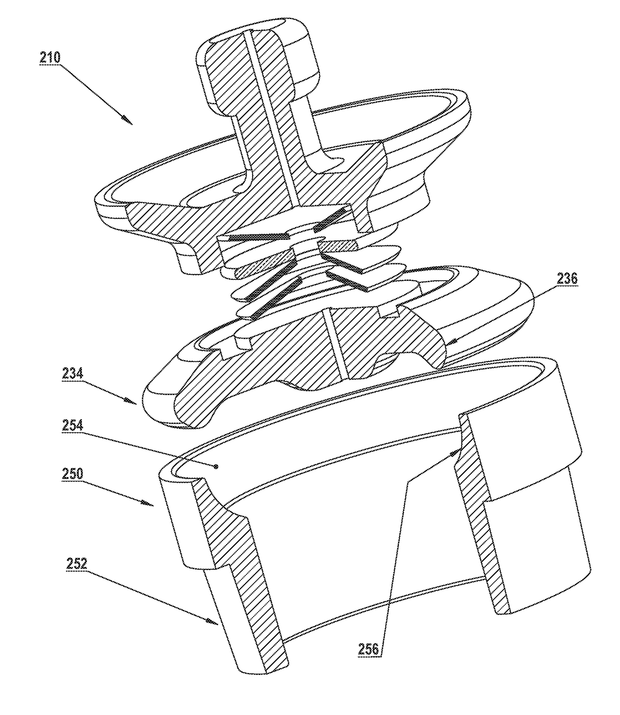
[0208]FIGS. 9-11 show schematic exploded views of a nonlinear spring-mass damper 227 / 228 / 229 / 230, which may be incorporated in a tunable check valve assembly embodiment 210. FIGS. 9-11 can each be understood as schematically illustrating a tunable check valve assembly with or without a peripheral groove viscoelastic element. That is, each figure may also be understood to additionally comprise a viscoelastic groove element analogous to groove element 54 (see FIG. 2) residing in groove 218′ / 218″ (see FIG. 9)—this groove element is not shown in exploded FIGS. 9-11 for clarity, but may be considered to comprise at least one circular tubular area analogous to tubular area 58 in groove element 54 (see FIG. 2), each tubular area 58 being substantially filled with at least one shear-thickening material 80 chosen to achieve at least one predetermined assembly resonant frequency.

[0209]Referring to FIG. 9, Belleville springs 227 / 228 / 229 are nonlinear, and they couple mass 230 to the valve body...


PUM


Abstract

Adaptive stimulation systems combine impulse-generated swept-frequency stimulation vibration with cyclically-varying hydraulic pressure to provide adaptive down-hole stimulation. Swept-frequency stimulation vibration arises from cyclical shifts of the power spectral density (PSD) of each stimulator's fluid interface vibration (via closed-loop control of the rebound cycle time and / or the fluid interface's effective elastic modulus). PSD's are adjusted for resonance excitation and fracturing of geologic materials at varying distances from a wellbore, closed-loop control incorporating backscatter vibration from stimulated geologic material. One or more stimulators generate vibration in bursts comprising a plurality of vibration frequencies. Timed signals from a programmable controller affect directional propagation of combined vibration wave fronts from a stimulator array. As fracturing proceeds to smaller (e.g., proppant-sized) fragments having higher resonant frequencies, PSD's are up-shifted, increasing relative stimulation vibration power in higher frequencies. Progressive stimulation is thereby optimized, facilitating plain-water (or liquefied propane) fracs with self-generated proppant.

Description

FIELD OF THE INVENTION[0001]The invention relates to control of impulse-generated (sometimes termed shock-generated) vibration for diagnostic testing and / or controlled fragmentation. Applications include vibration testing of geological strata or mechanical structures to characterize how inherent strengths and weaknesses affect their use. In the oil and gas industry, information from down-hole equipment develops control data which guides well completion. Particularly demanding applications include combining impulse-generated swept-frequency stimulation vibration with cyclically-varying hydraulic pressure (herein: adaptive stimulation) on intervals along horizontal wellbores in ultralow-permeability (unconventional) formations. The invention is related to U.S. Pat. Nos. 8,939,200, 8,944,409, 9,027,636, 9,080,690, and 9,169,707. The application is a continuation-in-part of co-pending U.S. patent application Ser. No. 14 / 919,848 (filed 22 Oct. 2015), and is related to co-pending U.S. pat...

Claims


Application Information

Patent Timeline
IPC IPC(8): E21B43/00E21B41/00E21B28/00E21B43/26E21B47/00E21B49/00G01V1/50G01V1/52
CPCE21B43/003E21B28/00E21B47/00E21B41/0092E21B43/26E21B49/00G01V1/523G01V1/50E21B47/12F16K15/06E21B43/2607
Inventor GILSTAD, DENNIS W.GILSTAD, BARBARA C.
Owner GILSTAD DENNIS W
Why Eureka
Try Eureka