Receiver with mutually coherent optical frequency combs

a mutually coherent optical frequency and receiver technology, applied in the field of hybrid, photonics-assisted receiver architecture based on mutually coherent frequency combs, can solve the problems of distinct implementation challenges, insufficient bandwidth, physical implementation, etc., and achieve the effects of preventing frequency reconfigurability, high tone count, and limited tone coun

Active Publication Date: 2018-01-04
RGT UNIV OF CALIFORNIA
View PDF0 Cites 31 Cited by
  • Summary
  • Abstract
  • Description
  • Claims
  • Application Information

AI Technical Summary

Benefits of technology

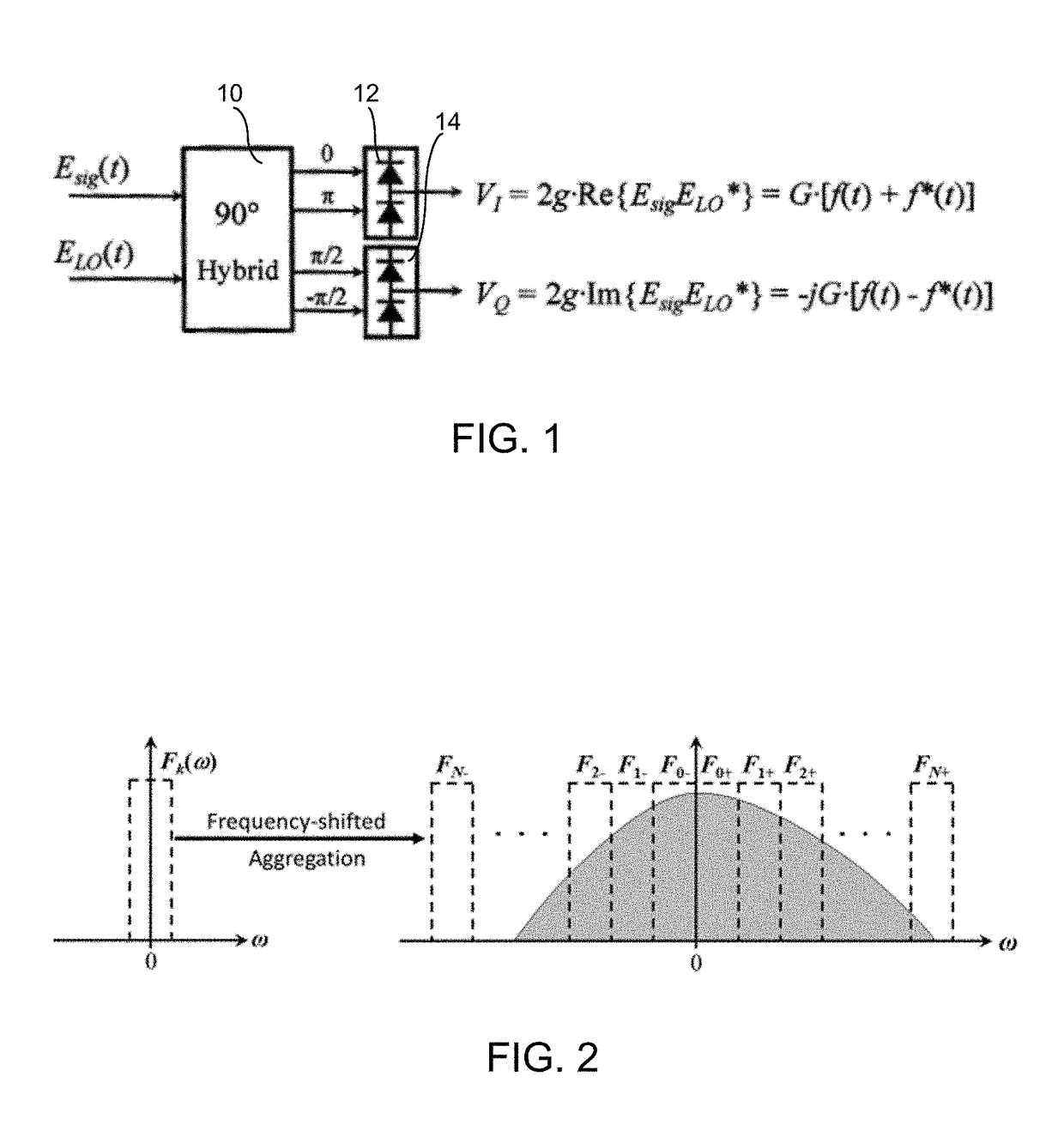
[0015]Physical access to complex transforms of a received signal eliminates the need for high-rate computation that must match the rate (bandwidth) of the incoming signal. In the example of ordinary (single-carrier) PPM demodulation, the frequency phase slope should be measured to estimate the received pulse position. Consequently, the resolution of the frequency decomposition should be sufficient to provide accurate pulse position estimation: the resolution in this case is directly proportional to the number of frequency comb tones used. Correspondingly, a wideband optical frequency comb with high tone count is superior but imposes distinct implementation challenges. Recognizing this, conventional comb generation techniques such as E / O-generated combs, resonator-seeded combs and mode-locked laser combs impose either limited tone count or prevent frequency reconfigurability. On the other hand, with the advent of shock-wave parametric mixers with hundreds of optical comb tone counts readily achievable, and frequency pitch reconfigurability, such mixers are desirable for their use in a comb based FH-PPM receiver. Additionally, any frequency comb that disconnects frequency tone pitch from a need to stabilize highly resonant cavity is also preferred for this implementation. While two combs that are generated using such cavities (resulting in different free-spectral range) can indeed be coherently coupled, this approach mandates an electronic feedback that, depending on optical path can have insufficient bandwidth.
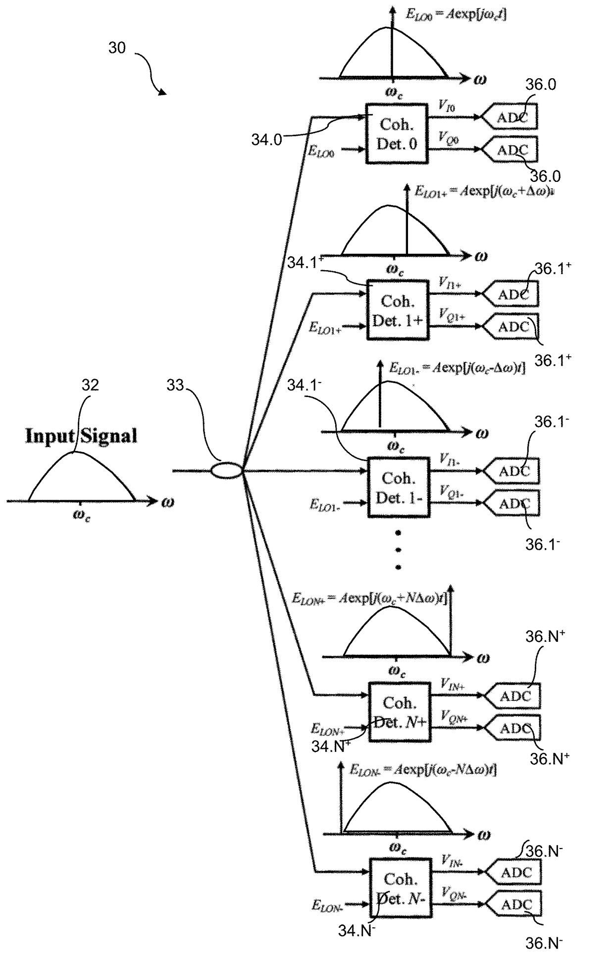
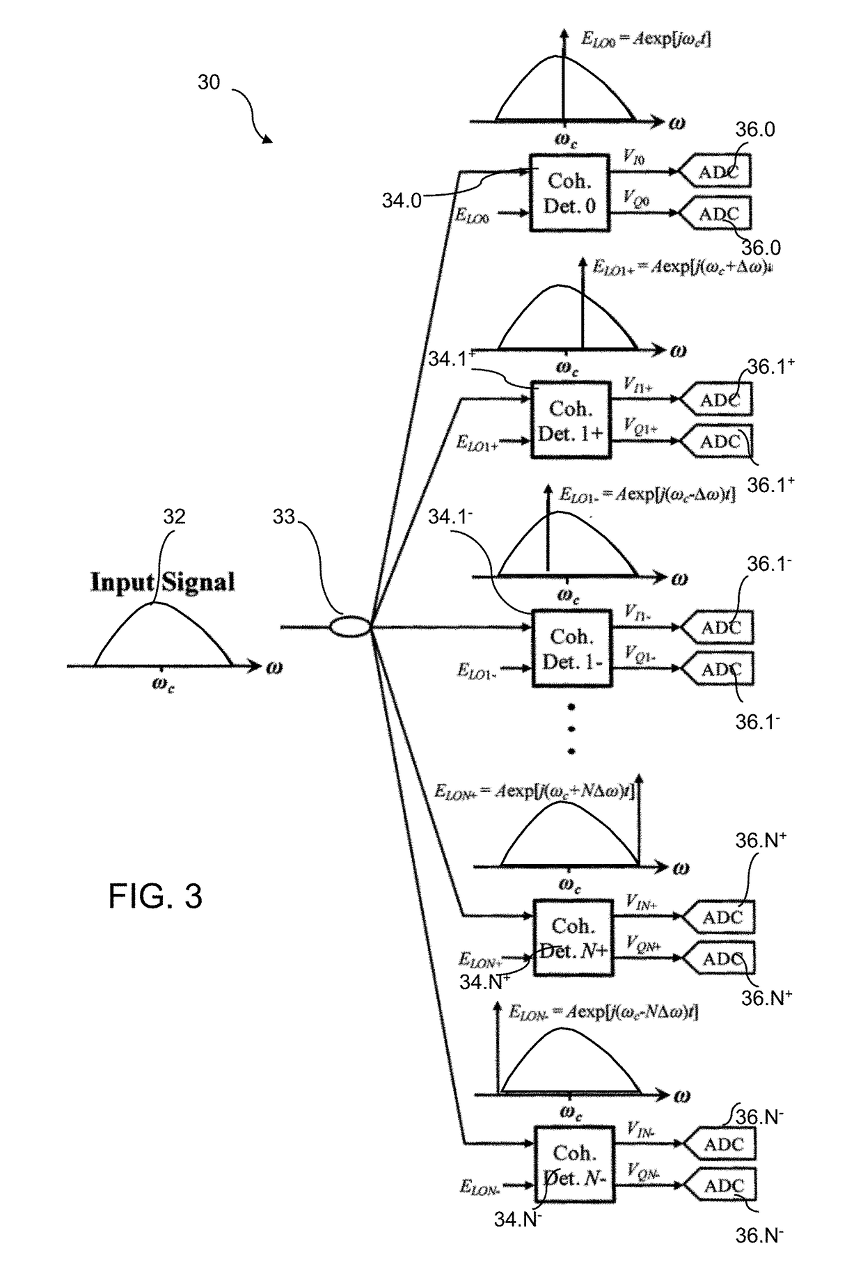
[0016]The inventive approach provides means for coherent spectral decomposition of a wide-band, high-speed optical signal, or an electrical signal via electrical / optical conversion, through coherent detection, without the need for narrow-band optical filtering to perform frequency slicing. The spectral decomposition reception architecture according to the invention enables real-time detection of a signal at sub-Nyquist receiver bandwidth. The inventive approach also circumvents the bandwidth-resolution of existing or conceivable analog-to-digital converters (ADCs), and alleviates the need for synthesizing physical channelization filters with excessive spectral isolation. In conventional approach, a perfect reconstruction of channelized signal requires the use of channelizer filters with brick-wall frequency response, which is not physically implementable. The all-DSP (digital signal processing) approach provided by the inventive method for image-rejection in coherent detection guarantees an ideal spectral response of the channelized receiver.

Problems solved by technology

Correspondingly, a wideband optical frequency comb with high tone count is superior but imposes distinct implementation challenges.
While two combs that are generated using such cavities (resulting in different free-spectral range) can indeed be coherently coupled, this approach mandates an electronic feedback that, depending on optical path can have insufficient bandwidth.
In conventional approach, a perfect reconstruction of channelized signal requires the use of channelizer filters with brick-wall frequency response, which is not physically implementable.
While a bank of filters could be utilized to provide contiguous frequency array, such approach would also impose implementation challenges.

Method used


Image

  • Receiver with mutually coherent optical frequency combs
  • Receiver with mutually coherent optical frequency combs
  • Receiver with mutually coherent optical frequency combs

Examples


example 1

band (UWB) Secure Wireless Communication

[0072]In the example of ordinary (single-carrier) PPM demodulation, the frequency phase slope should be measured to estimate the received pulse position. Consequently, the resolution of the frequency decomposition should be sufficient to provide accurate pulse position estimation: the resolution in this case is directly proportional to the number of frequency comb tones used. Correspondingly, a wideband optical frequency comb with high tone count is superior but imposes distinct implementation challenges. Recognizing this, conventional comb generation techniques such as E / O-generated combs, resonator-seeded combs and mode-locked laser combs impose either limited tone count or prevent frequency reconfigurability. On the other hand, with the advent of shock wave and comparable performance parametric mixers with hundreds of optical comb tone counts readily achievable, and frequency pitch reconfigurability, such mixers are desirable for their use ...

example 2

ionary Analysis

[0086]In cyclostationary (CS) analysis, spectral computation must be performed over multiple modulation cycles. A conventional cyclostationary receiver must perform DFT in real-time in order to complete the acquisition chain. Current all-electronics DFT technology limits real-time spectral bandwidth to sub-GHz-scale range—two orders of magnitude below the needs of future EW spectral range (>110 GHz).

[0087]Incorporation of the inventive mutually-coherent frequency comb structure into a CS analyzer architecture for signal replication and frequency decomposition can completely eliminate a high bandwidth ADC and dispenses with the need for computational Fourier mapping of the received emission.

example 3

Pattern Recognition

[0088]Real-time pattern recognition poses technology limit in both imaging, SIGINT and cyber-defense fields. Terabit-per-second-capacity lightwave channels that carry high-capacity terrestrial and submarine fiber data traffic present an enormous challenge to analyze an anomalous traffic pattern in real time. In practical terms, this means that DFT of Terabit-class stream must be computed at wirespeed, i.e., at latency that is comparable to a lightwave packet traversing the localized segment of fiber. A DFT coprocessor architecture that employs the physically-assisted computing enabled by the mutually-coherent frequency comb of the present invention would be capable of real-time, continuous operation that approaches or even matches a lightwave channel rate.


PUM


Abstract

A receiver architecture for physically-assisted computing of transforms, such as discrete Fourier transforms (DFT) and discrete Hilbert transforms (DHT), employs mutually-coherent optical frequency combs for detection of the coherent beating between an optical signal and a reference optical tone generated by a local oscillator (LO). A signal replication mixer generates a plurality of signal optical tones having a frequency pitch with an input signal mapped thereon. A reference mixer (local oscillator) generates a plurality of reference optical tones having an offset frequency pitch relative to the signal tones. A receiver backplane detects coherent beating between the signal optical tones and the reference optical tones. The input signal may be in the optical domain or in the radio-frequency domain.

Description

RELATED APPLICATIONS[0001]This application claims the benefit of the priority of U.S. Provisional Application No. 62 / 358,120, filed Jul. 4, 2016, the disclosure of which is incorporated herein by reference in its entirety.FIELD OF THE INVENTION[0002]The present invention relates to a hybrid, photonics-assisted receiver architecture based on mutually-coherent frequency combs.BACKGROUND OF THE INVENTION[0003]Discrete Fourier Transform (DFT) processors are one the most important class of specialized computing engines used for signal and image processing in disciplines ranging from electronic warfare (EW), cyber-security, optical and wireless communications, image processing and spectroscopy. Conventional DFT processor implementation rests on reduced-complexity algorithms such as split-radix FFT (SRFFT) that approach the lower bound on number of multiplications predicted by Winograd (Mathematics of Computation, 32(141):175-199, 1978). However, a typical 256-bit FFT operation still uses ...

Claims


Application Information

Patent Timeline
Patent Type & Authority Applications(United States)
IPC IPC(8): H04B10/61H04J14/02
CPCH04B10/616G02F2203/56H04B2210/006H04J14/02
Inventor KUO, PING PIURADIC, STOJAN
Owner RGT UNIV OF CALIFORNIA
Why Eureka
Try Eureka