
Radio frequency electro-thrombectomy device

a radio frequency electrothrombus and thrombosis technology, applied in the field of radio frequency electrothrombus devices, can solve the problems of insufficient oxygen to cells, inability to carry out surgery, damage to the vessel wall, etc., and achieve the effects of minimizing the risk of vessel wall damage, enhancing the adhesion between the device and the device, and reducing the risk of thrombosis

Active Publication Date: 2018-05-24
THE HONG KONG UNIV OF SCI & TECH
View PDF5 Cites 60 Cited by
  • Summary
  • Abstract
  • Description
  • Claims
  • Application Information

AI Technical Summary

Benefits of technology

The present invention provides a device for removing blockages in blood vessels that reduces the risk of damage to the vessel wall and blockage fragmentation. This is achieved by using RF electric current to strengthen the blockage and the device's interface prior to removal. The device can immediately recanulate a blocked blood vessel and minimize damage to the vascular system by applying RF electric current to stabilize the blockage and enhance adhesion between the device and the blockage. This increases the fracture resistance of the blockage and the interfacial fracture resistance between the device and the blockage.

Problems solved by technology

Blockage-related diseases such as ischemic stroke in different organs, including the brain and the heart, are common causes of death.
Although a thrombus is a healthy response to injury intended to prevent bleeding, a thrombus can become harmful in thrombosis when blot clots obstruct blood flow through healthy vessels.
If the perfusion is below a certain level, cells receive insufficient amount of oxygen and will perish if the situation is prolonged.
A venous embolus travels to the right side of the heart and through the pulmonary artery and leads to pulmonary embolism, while an arterial embolus can occlude any artery or arteriole downstream of the thrombus formation and can lead to cerebral stroke, myocardial infarction, or infarction in any other organ.
Chemical thrombolysis achieves some success in acute ischemic stroke, but because of the high risk of side effects, such as symptomatic intracerebral hemorrhage (sICH), and limited treatment time window, only 10% of patients are eligible for the treatment.
In addition, chemical thrombolysis when applied alone has low recanalization rates and often requires continuous treatment for up to one week.
However, complications such as blockage fragmentation with the risk of distal embolization and vascular damage that can cause restenosis are major concerns.
However, the continuous infusion and removal of drug renders control of drug dosage difficult.
Beside the difficulty of controlling drug dosages delivered utilizing any of these devices, drug delivery cannot be restricted to certain localizations.
In addition, thrombolytic recanalization is not effective in all cases, might require an extended time of treatment, and often has to be combined with mechanical means of blockage removal.
These devices lack bulk strengthening function and interfacial strengthening function may lead to blockage fragmentation.
Devices that use radial force to capture the blockage may lead to vascular damages.
However, such device does not allow the removal of material and leaves the heated clot in the vessel.
However, the blockage is not strengthened during the procedure and the efficient removal of the entire blockage depends on the complete capture of embolizing fragments in the filter / cage, whereby the size of the filter or cage must be selected appropriately to contain the entire volume of the ablated blockage material, due to the inability to perform the procedure in multiple steps.
Although the latter methods allow sequential retrieval of material dislodged from a thrombus or embolus, the devices have no effect on the stability or lack thereof of the thrombus and / or embolus material remaining as the removal procedure progresses.
However, the heating is non-uniform and diminishes as a function of distance away from the wire, such that the strengthening of materials at the periphery would require high heat at the wire, which may damage the nearby vessel wall.

Method used


Image

  • Radio frequency electro-thrombectomy device
  • Radio frequency electro-thrombectomy device
  • Radio frequency electro-thrombectomy device

Examples


Embodiment Construction

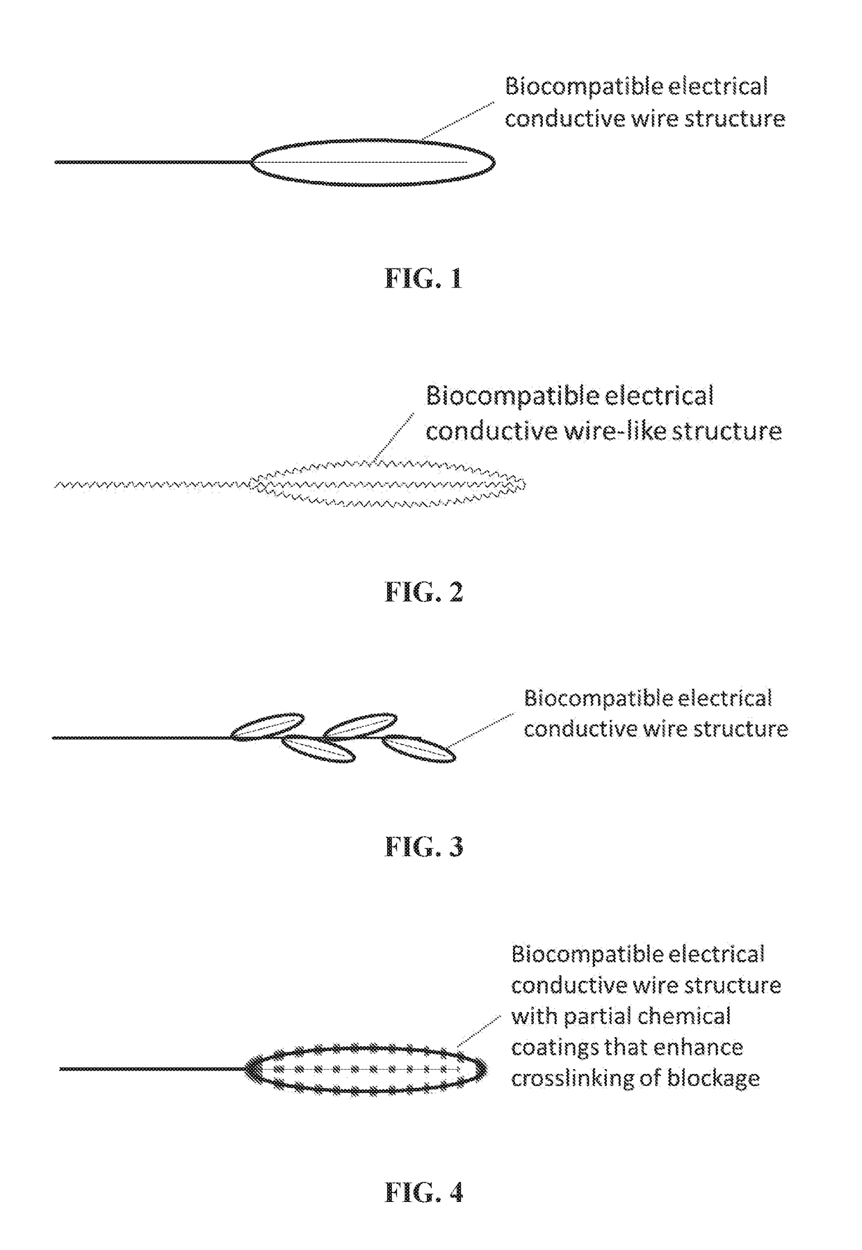
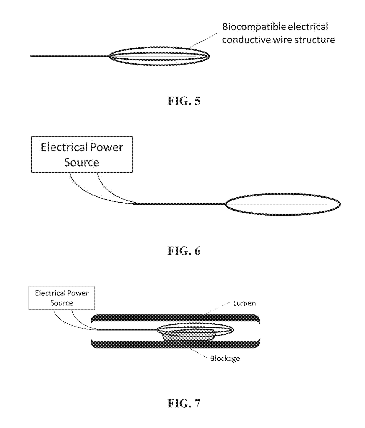
[0023]The present invention provides a RF electro-thrombectomy device for removal of vascular lumen blockages with a low risk of vessel wall damage and blockage fragmentation due to the use of RF electric current to strengthen the blockage and the blockage-device interface prior to blockage removal. The blockage removal device of the present invention causes an electric current, such as RF or direct electric current, to pass through a blockage, which lumen blockage can be, but are not limited to, a thrombus, blood clot or embolus.

[0024]Embodiments of the RF electro-thrombectomy device are generally made of electrically conductive and optionally biocompatible, conducting wires, manipulation wire, and a structure that is designed to capture a vascular blockage, connected to an RF system. An RF system generates an RF electric current. A preferred embodiment of the RF electro-thrombectomy device comprises at least one biocompatible, manipulation wire and a structure. In some embodiments...


PUM


Abstract

A device is designed to remove blockages in a lumen such as a thrombus, blood clot, or embolus. The device comprises a manipulating wire and a structure that can conduct electrical current to a lumen blockage. The electrical current is preferably in radio frequency (RF). The RF electric current in the blockage can excite the contents such as proteins of the blockage, so that cross-linking density and interfacial adsorption of the entire blockage is enhanced. The enhanced cross-linking density can result in increased fracture resistance of the blockage such that fracture of the blockage during the removal process is unlikely. The enhanced interfacial adsorption results in increased interfacial fracture resistance between the device and blockage so that the blockage can be securely captured during the removal process without using radially applied force.

Description

BACKGROUND OF THE INVENTION[0001]Blockage-related diseases such as ischemic stroke in different organs, including the brain and the heart, are common causes of death. A blockage in a vessel lumen, which can be a thrombus, blood clot or embolus, can lower blood perfusion of the downstream tissues. A thrombosis is the formation or presence of a thrombus or blood clot inside a blood vessel or cavity of the heart. There are two main components of a thrombus, aggregated platelets that form a platelet plug and a mesh of cross-linked fibrin protein. Although a thrombus is a healthy response to injury intended to prevent bleeding, a thrombus can become harmful in thrombosis when blot clots obstruct blood flow through healthy vessels. An embolus is a thrombus or blood clot that moves through the blood stream until it lodges in a narrowed vessel and blocks blood circulation. If the perfusion is below a certain level, cells receive insufficient amount of oxygen and will perish if the situation...

Claims


Application Information

Patent Timeline
Patent Type & Authority Applications(United States)
IPC IPC(8): A61B18/14A61B17/221
CPCA61B18/1492A61B17/221A61B2018/00214A61B2017/22034A61B2018/1475A61B2018/0041A61B2018/144A61B2018/00267A61B2018/00398A61B2018/00404
Inventor LAM, DAVID CHUEN CHUNCHON, CHI HANGKWOK, JOHN CHING KWONGYUEN, MATTHEW MING FAIQIN, ZHENLAM, ALEXANDER KA NGAI
Owner THE HONG KONG UNIV OF SCI & TECH
Learn More