MEMS transducer for interacting with a volume flow of a fluid and method for manufacturing the same

a technology of volume flow and mems, which is applied in the direction of piezoelectric/electrostrictive devices, chemical vapor deposition coating, decorative arts, etc., can solve the problems of complex integration of ceramic functional layers, operation may not be performed without hysteresis, and the mems loudspeaker is currently not significantly commercialized. , to achieve the effect of high efficiency, high efficiency and efficient manner

Active Publication Date: 2018-06-28
FRAUNHOFER GESELLSCHAFT ZUR FOERDERUNG DER ANGEWANDTEN FORSCHUNG EV
View PDF0 Cites 36 Cited by
  • Summary
  • Abstract
  • Description
  • Claims
  • Application Information

AI Technical Summary

Benefits of technology

[0027]The core idea of the present invention is to have recognized that the above-mentioned object may be solved by the fact that a volume flow of a fluid may be affected in an especially efficient manner by means of an element which is deformable along a lateral movement direction, or by the fact that the volume flow may deflect such an element in an especially efficient manner. The lateral movement direction, possibly perpendicular to a direction of the fluid flow, enables large areas of the deformable element which may interact with the volume flow, with simultaneously having small dimensions of a chip surface so that, overall, an efficient MEMS transducer device with a high efficiency is obtained.
[0028]According to an embodiment, a MEMS transducer for interacting with a volume flow of a fluid includes a substrate comprising a cavity, and an electromechanical transducer connected to the substrate and comprising an element deformable along a lateral movement direction, wherein a deformation

Problems solved by technology

Electroacoustic MEMS loudspeakers are currently not significantly commercialized.
A disadvantage of piezoelectric functional layers is the fact that the operation may not be performed without hysteresis.
Furthermore, the integration of the ceramic functional layers is complex and, due to the lack of CMOS compatibility (CMOS=complementary metal oxide semiconductor), only possible under strict contamination control or in a separate clean room area when using PZT and ZnO.
The structure is voluminous, complex and does not seem to be scalable in a meaningful way with respect to large quantities.
Usually, the coil is integrated into the membrane by depositing and structuring a metal layer, and a permanent magnet is added as an external component during assembly The complexity and the limitations with respect to the inte

Method used


Image

  • MEMS transducer for interacting with a volume flow of a fluid and method for manufacturing the same
  • MEMS transducer for interacting with a volume flow of a fluid and method for manufacturing the same
  • MEMS transducer for interacting with a volume flow of a fluid and method for manufacturing the same

Examples


Embodiment Construction

[0067]Before embodiments of the present invention are subsequently explained detail with reference to the drawings, it is pointed out that identical, functionally identical and operatively identical elements, objects and / or structures are provided in the different figures with identical reference numerals so that the description of these elements in different embodiments is interchangeable and / or mutually applicable.

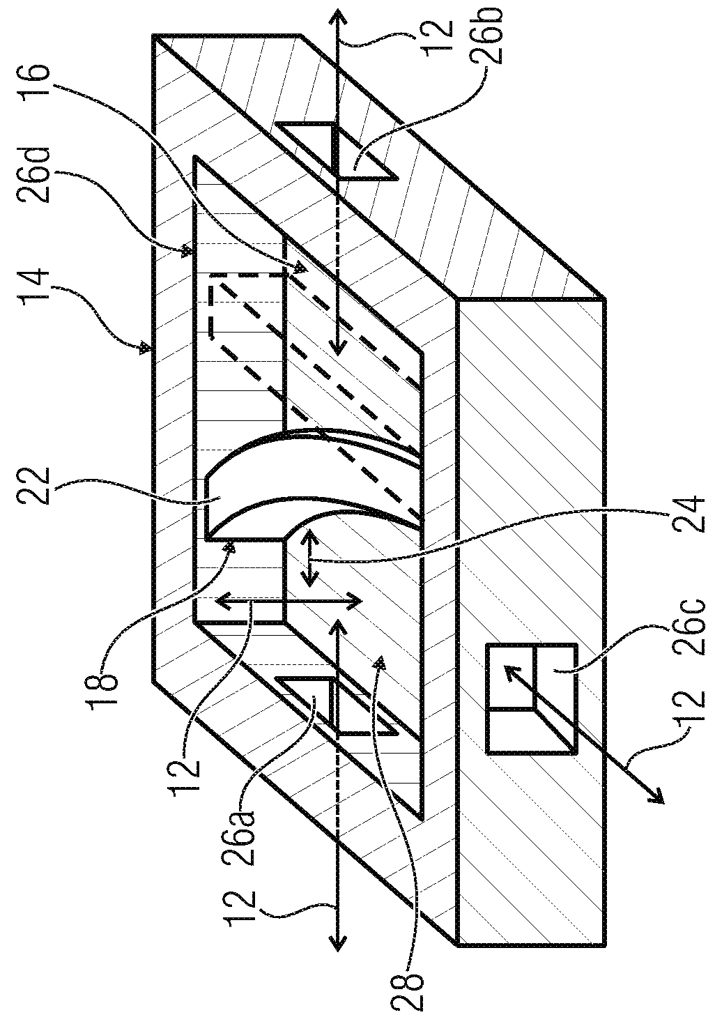
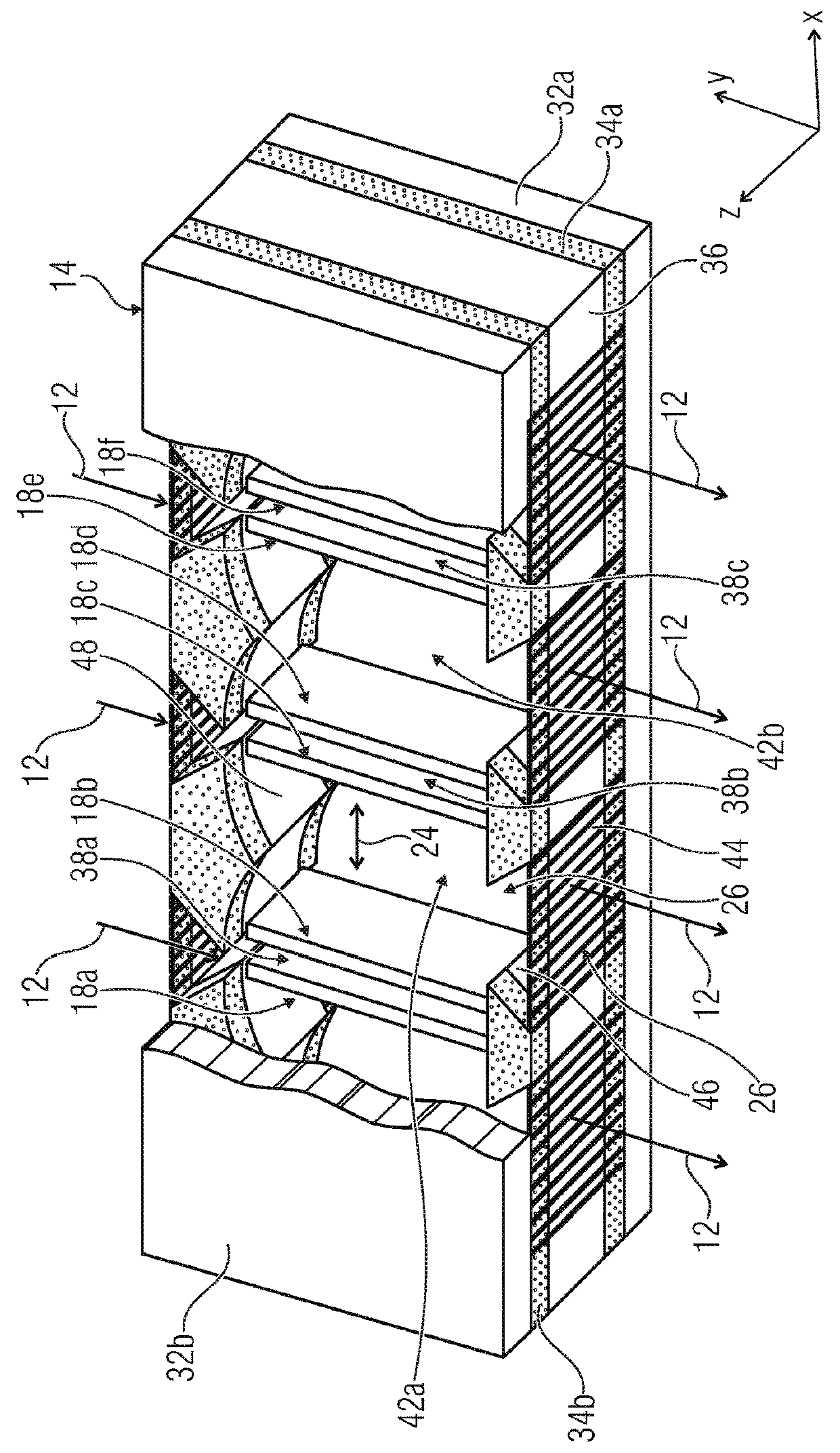
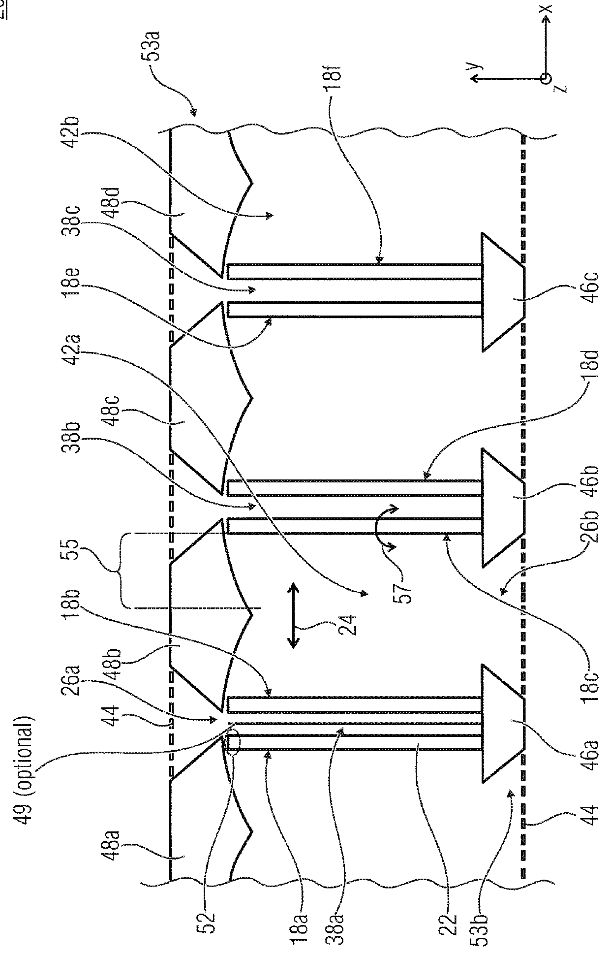
[0068]Subsequently, reference is made to MEMS transducers (MEMS=microelectromechanical system). A MEMS transducer may comprise one or several electroactive components causing a change of a mechanical component based on an applied electric quantity (current, voltage, charge or the like). For example, this change may relate to deformation, heating or tension of the mechanical component. Alternatively or additionally, a mechanical influence on the component, e.g., deformation, heating or tension may lead to an electric signal or to an electric information (voltage, current,...


PUM

PropertyMeasurementUnit
Lengthaaaaaaaaaa
Lengthaaaaaaaaaa
Lengthaaaaaaaaaa

Abstract

A MEMS transducer for interacting with a volume flow of a fluid includes a substrate including a cavity, and an electromechanical transducer connected to the substrate in the cavity and including an element deformable along a lateral movement direction, wherein a deformation of the deformable element along the lateral movement direction and the volume flow of the fluid are causally related.

Description

CROSS-REFERENCES TO RELATED APPLICATIONS[0001]This application is a continuation of copending International Application No. PCT / EP2016 / 063611, filed Jun. 14, 2016, which is incorporated herein by reference in its entirety, and additionally claims priority from German Application No. DE 10 2015 210 919.4, filed Jun. 15, 2015, which is incorporated herein by reference in its entirety.BACKGROUND OF THE INVENTION[0002]The present invention relates to a MEMS transducer for interacting with a volume flow of a fluid, e.g., a MEMS loudspeaker, a MEMS microphone or a MEMS pump. Furthermore, the present invention relates to a method for manufacturing a MEMS transducer. Furthermore, the present invention relates to a MEMS-based electroacoustic transducer.[0003]In addition to the miniaturization, one focus of the MEMS technology (MEMS—microelectromechanical system) particularly lies in the potential for a cost-effective manufacturability of the component in medium and high quantities. Electroac...

Claims


Application Information

Patent Timeline
IPC IPC(8): B81B3/00H04R19/00B81C1/00
CPCB81B3/0021H04R19/005B81C1/0015B81C1/00158B81C1/00142B81B2201/0257B81B2203/051H04R2201/003B81B2201/036B81B2203/0118B81B2203/0136B81B2203/0109B81B2203/0127B81B2203/019H04R1/023H04R1/08H04R9/02H04R15/00H04R17/00H04R23/002H04R2499/11B81C1/00182B81B2203/0172B81B2201/054B81B2201/032
Inventor SCHENK, HARALDCONRAD, HOLGERGAUDET, MATTHIEUSCHIMMANZ, KLAUSLANGA, SERGIUKAISER, BERT
Owner FRAUNHOFER GESELLSCHAFT ZUR FOERDERUNG DER ANGEWANDTEN FORSCHUNG EV
Why Eureka
Try Eureka