
Optical communication module configured for enhancing optical coupling efficiency

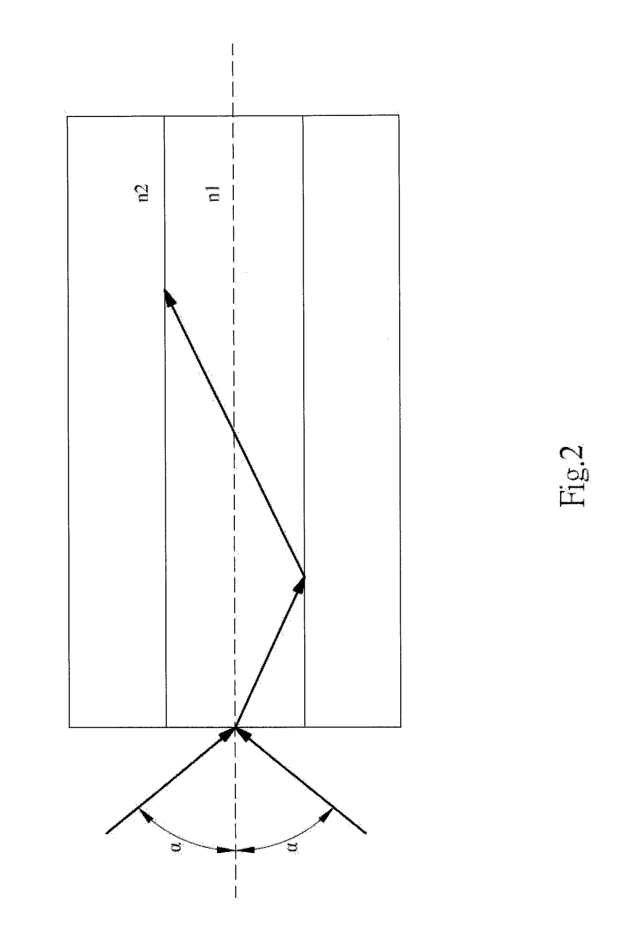
a communication module and optical coupling technology, applied in the field of optical communication modules, can solve the problems of reducing the yield of the resulting module, limiting the tolerance of optical coupling positions, and affecting the efficiency of optical coupling,

Inactive Publication Date: 2018-07-05
LUXNET CORP
View PDF17 Cites 2 Cited by
  • Summary
  • Abstract
  • Description
  • Claims
  • Application Information

AI Technical Summary

Benefits of technology

The present invention provides an optical communication module with enhanced optical coupling efficiency. This is achieved by using optical fibers with two different numerical apertures, one for light-receiving and one for light-coupling. This solves the issue of poor coupling efficiency in conventional optical fiber butt joint receptacles that have only single numerical aperture. Additionally, the invention reduces reflection loss between two different optical fibers and increases their optical coupling efficiency by forming a fused conical taper or providing a coupling structure and index coupling material between them.

Problems solved by technology

A small-NA optical fiber can receive light over only a small range of angles and may present difficulties, or cause excessive loss, in optical coupling, thus limiting the tolerances of optical coupling positions and lowering the yield of the resulting module.
SMF-28 is a standard, and hence low-cost, optical fiber, but its small numerical aperture and small core diameter tend to hinder optical coupling or incur great coupling loss.
However, it is time-consuming and labor-intensive for obtaining the relative maximum coupling power value.
Meanwhile, in order to obtain the best coupling power value, the light-receiving angle may shift horizontally, and such coupling may not meet the mechanical requirement.
Moreover, sometimes the horizontal shifting still cannot satisfy the maximum coupling efficiency, so that it is necessary to tilt the end-face of the optical fiber having a specific angle to obtain the maximum coupling power.
However, such method is contrary to the actual requirement of the general communication elements that are flat and sealed after coupling.
In addition, if the angle of the incident laser light is very small or does not deviate from the optical axis angle but the end-face of the single-mode optical fiber core has a specific angle by cutting, parts of the light beam would fall into angles outside the specific cone angle and the actual maximum optical power value cannot be obtained.
Such trial-and-error angle matching is time-consuming and labor-intensive, and cannot enhance the production efficiency for the optical communication module.
Although such design increases the receiving area and angle of the incident plane and use of the multi-mode optical fiber as the external optical fiber can connect without lose, when connecting to the outer single-mode optical fiber, it is easy to cause greater loss at the junction of the fibers during signal transmission owing to the core diameter of the multi-mode fiber (fiber core) is larger than that of the single-mode optical fiber (external fiber).

Method used


Image

  • Optical communication module configured for enhancing optical coupling efficiency
  • Optical communication module configured for enhancing optical coupling efficiency
  • Optical communication module configured for enhancing optical coupling efficiency

Examples


first embodiment

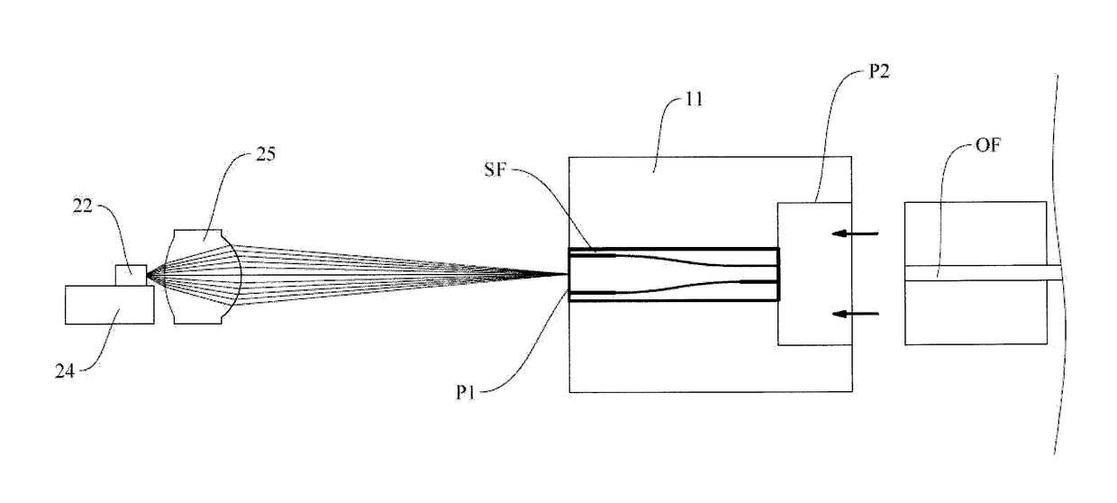
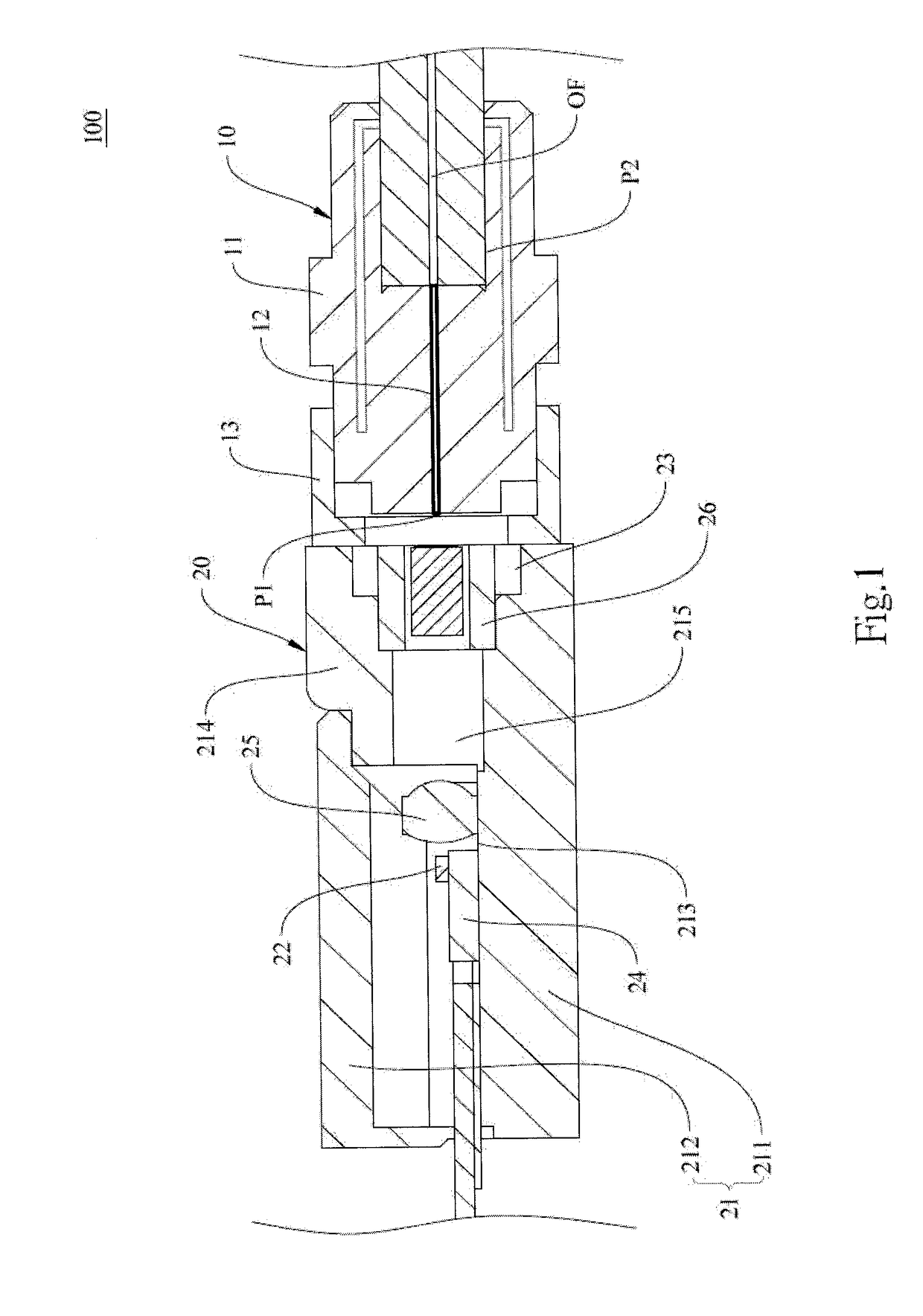
[0056]Referring to FIG. 3 and FIG. 4 respectively for a functional block diagram and a schematic sectional view of the present invention.

[0057]In this embodiment, the dual-core optical fiber has a light-receiving section and a light-coupling section, which are joined together by a fused conical taper method to form a single unit cone optical fiber as a light-coupling section. To carry out the fused conical taper method, two optical fibers have to be prepared, and in this embodiment, an optical fiber with a relatively large numerical aperture (e.g., an MMF or a special SMF) and an optical fiber whose core diameter is not larger than or is close to that of the external optical fiber OF or whose mode field diameter is equal to that of the external optical fiber OF (e.g., an SMF) are required. The to-be-joined portions of the two optical fibers are fused together by being subjected to a temperature above 1400° C. but not higher than 1700° C. The fused and subsequently solidified portion...

second embodiment

[0062]Another preferred embodiment of the present invention is described below with reference to FIG. 5 and FIG. 6, which are a functional block diagram and a schematic sectional view of the second embodiment respectively.

[0063]Unlike the previous embodiment, in which a single tapered optical fiber SF is fitted into the through hole 12 of the receptacle body 11, the dual-core optical fiber in the preferred embodiment includes a coupling structure provided between the light-receiving section IF1 and the light-coupling section IF2 such that a linked optical fiber IF with different numerical apertures or core diameters is formed. More specifically, optical fibers of different numerical apertures or core diameters are fitted into the through hole 12 to serve as the light-receiving section IF1 and the light-coupling section IF2 respectively. The coupling structure between the light-receiving section IF1 and the light-coupling section IF2 is configured to concentrate the light beam propag...

third embodiment

[0068]Referring now to FIG. 7 for a schematic sectional view of the present invention.

[0069]This embodiment is different from the previous ones only in the way in which the coupling structure of the linked optical fiber is implemented, so the remaining portions will not be described repeatedly.

[0070]In this embodiment, the linked optical fiber JF has a light-receiving section JF1 and a light-coupling section JF2. The end of the light-receiving section JF1 that is adjacent to the light-coupling section JF2 has a concave sintered surface JF11. On the opposite side of this concave surface JF11, the light-coupling section JF2 has an end adjacent to the light-receiving section JF1 and formed with a concave sintered surface JF21. A condensing lens JF3 is provided between the concave surfaces JF11 and JF21 to focus the laser beam in the light-receiving section JF1 on the light-coupling section JF2, thereby reducing the coupling loss between the light-receiving section JF1 and the light-cou...


PUM


Abstract

An optical communication module configured for enhancing optical coupling efficiency, which includes an optical butt joint receptacle and a light emitting body provided on one side of the optical butt joint receptacle. The optical butt joint receptacle has a receptacle body and a through hole provided in the receptacle body for a dual-core optical fiber to extend through. The receptacle body has a light-receiving side and an optical fiber insertion groove corresponding respectively to two ends of the through hole. The light emitting body includes a housing, a laser semiconductor provided in the housing, and an aperture provided in one side of the housing for aligning with the through hole so as that the laser beam emitted by the laser semiconductor is optically coupled to the dual-core optical fiber. The dual-core optical fiber has different core diameters and numerical apertures to enhance the coupling efficiency and reduce the coupling loss in between with the external optical fiber.

Description

BACKGROUND OF THE INVENTION1. Technical Field[0001]The present invention relates to an optical communication module, especially to an optical communication module configured for enhancing optical coupling efficiency.2. Description of Related Art[0002]In an optical communication system, the numerical aperture (NA) of an optical fiber determines the range of angles over which the optical fiber can receive light and therefore must be considered when guiding a light beam into the optical fiber. A small-NA optical fiber can receive light over only a small range of angles and may present difficulties, or cause excessive loss, in optical coupling, thus limiting the tolerances of optical coupling positions and lowering the yield of the resulting module.[0003]Generally, the fiber core of an optical fiber butt joint receptacle is composed of an SMF-28 single-mode optical fiber, whose numerical aperture (NA=0.14, with the optical signal wavelength being 1310 nm) and core diameter (8.2 μm) requ...

Claims


Application Information

Patent Timeline
IPC IPC(8): G02B6/42
CPCG02B6/4206G02B6/423H04B10/25H04B10/503G02B6/02042G02B6/4208G02B6/4243G02B6/4292
Inventor LAW, PI-CHENGHUANG, PO-CHAOLIU, PO-SUNGLIN, HSING-YENSU, HUA-HSIN
Owner LUXNET CORP
Learn More