Circulating inert-gas seal system based on gas-supply servo device and QHSE based storage and transportation method

a gas-supply servo and gas-supply pipeline technology, applied in pipeline systems, container discharging methods, container filling methods, etc., can solve problems such as environmental pollution and safety hazards at the pressure relief valve port, over-all chemical explosion attacks, and run counter to on

Inactive Publication Date: 2018-08-02
SUN QIANGDAN
View PDF0 Cites 12 Cited by
  • Summary
  • Abstract
  • Description
  • Claims
  • Application Information

AI Technical Summary

Benefits of technology

[0015]An eighth object of the present invention is to provide a QHSE storage and transportation method based on the circulating inert-gas seal system, which is capable of avoiding atmospheric forced sampling mode inspection by a manner of without gas phase discharge.
[0016]A ninth object of the present invention is to provide a QHSE storage and transportation method based on the circulating inert-gas seal system, which is capable of generating a defensive force coping with the detonation of the incoming warhead in a container.

Problems solved by technology

However, under the current background of contemporary attack forces, which are commonly deployed and commonly encountered in actual combat and normal deterrence, the front-stage earth-boring and / or container detonation, and then devastated oil and gas, detonated materials, resulting in the overall chemical explosion attack after the significant damage, cost-effective, is to destroy the military oil supply project, the national strategic reserve, chemical industry park, and ship, ship power oil cabinet, roads, railway tankers and other important military and economic goals of the basic model, the election of the best species and tactics.
However, the conventional art in different areas involving bulk liquid hazardous chemicals and containers often run counter to one another.
However, air pollution caused by the continuity of the volatile, escape on the sealing device has not been included as a mandatory control areas; the conventional floating roof with nitrogen sealing technology further ensures the system oxygen safety and inhibits material oxidation and deterioration, but while the mass transfer products are expelled from the storage tank and accompanied by the process of nitrogen bleed, the environmental pollution and the safety hazard at the pressure relief valve port have not been solved yet.
The conventional self-sealing gas-liquid exchange recovery technology reduces the material handling, but the air serves as a medium to balance the import and export side of the container process, which causes a result that that explosion risk of the container material mixture in the output side suddenly increases, and the recycling technique is not suitable for all types of floating roof tank.
Although the technical solution achieves the technical purpose of filling the gaseous space of the material container with the circulating gaseous inert medium, the method is capable of controlling the normalization of the oxygen content less than the limit of the combustion and explosion of the protected material and capable of permanently suppressing the combustion and explosion conditions of the hazardous chemicals in the container However, this solution only gives a general realization of the gaseous inert medium source, and fails to focus on the internal structure of the inert media source, the connection relationship, as well as control methods and technical requirements for material container group and storage chain network.

Method used


Image

  • Circulating inert-gas seal system based on gas-supply servo device and QHSE based storage and transportation method
  • Circulating inert-gas seal system based on gas-supply servo device and QHSE based storage and transportation method
  • Circulating inert-gas seal system based on gas-supply servo device and QHSE based storage and transportation method

Examples


second embodiment

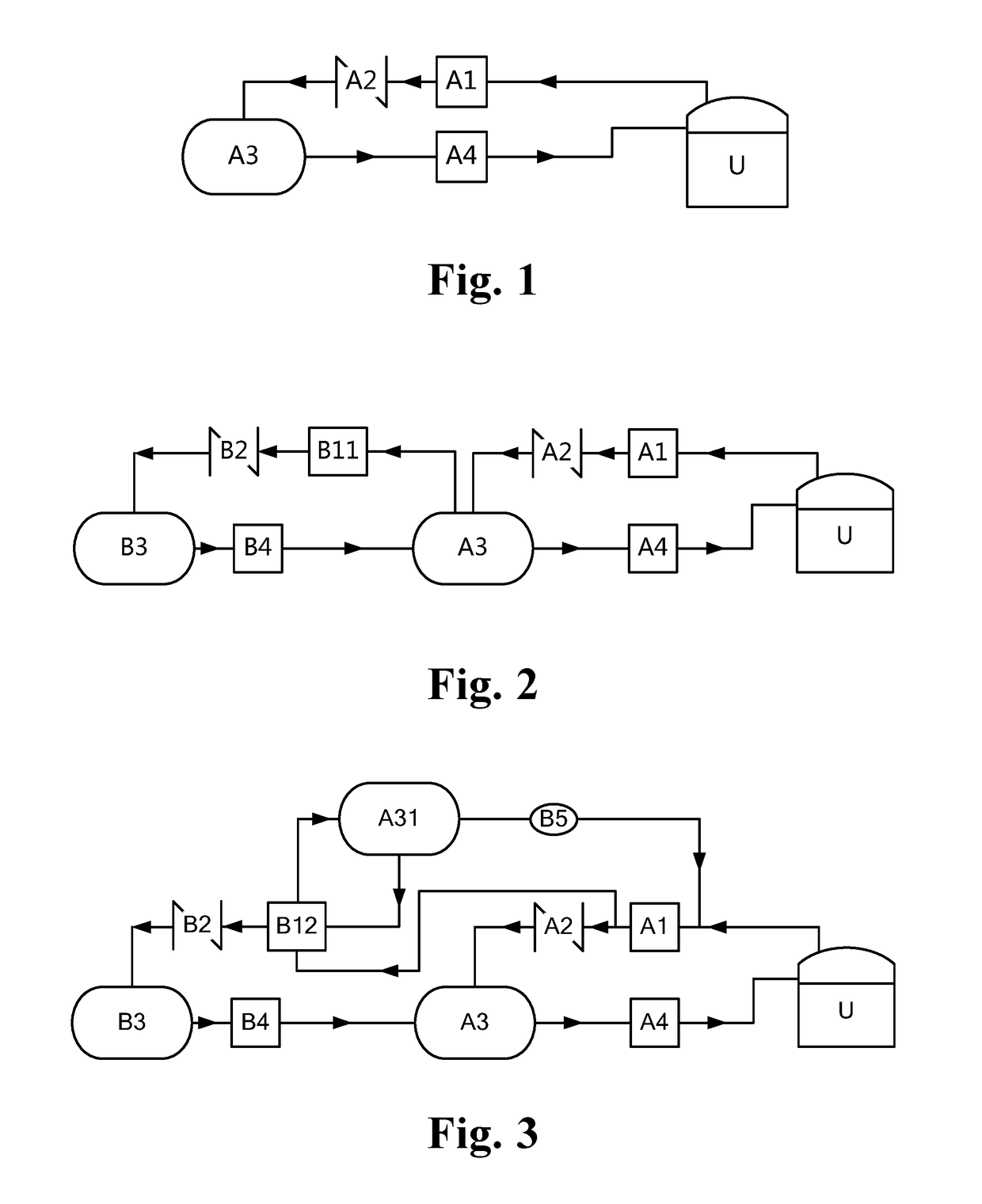
[0118]FIG. 2 is a schematic diagram of a cycle inert sealing system according to the present invention. Compared with the previous embodiment, the gas source servo device in this embodiment may further include a gas source turnover unit in control connection with the servo constant pressure unit for expanding the working gas volume circulated in the gas source servo device, And support the working gas for external output and / or internal input. Specifically, the gas source turnover unit includes a gas storage booster (preferably an electric booster B11), a check valve B2, a surge tank B3 and a make-up valve control Component B4.

[0119]The air inlet of the air compressor is connected to the air source container A3 in a one-way manner and is valve-controlled, and can start and stop the interlocking with automatic, interlocking and\or manual mode control to output the air source container A3 Of the working gas, further compressed and filled to the working container B3, and fed back to co...

third embodiment

[0125]As shown in FIG. 3, which is a schematic diagram of the principle of the circulating inert seal system of the present invention. Compared with the previous embodiment, this embodiment shows another structure of the gas source turnover unit. The utility model specifically comprises a gas storage booster, a filling check valve B2, a turnover container B3 and a compensating valve assembly B4 which are connected in turn and are in one-way valve control. The gas storage turbocharger is a gas turbocharger B12. The gas turbocharger B12 has a driving gas input interface, a driving gas output interface, a working gas inlet and a working gas outlet. The gas drive turbocharger B12 is also equipped with a relay vessel A31, a drive gas circulation pipe and a circulation gas pressure release valve B5 for driving the working gas discharged from the gas compressor A1 as the driving gas for the gas-boosting compressor B12 Its running.

[0126]The air outlet of the air compressor A1 and the drivin...

fourth embodiment

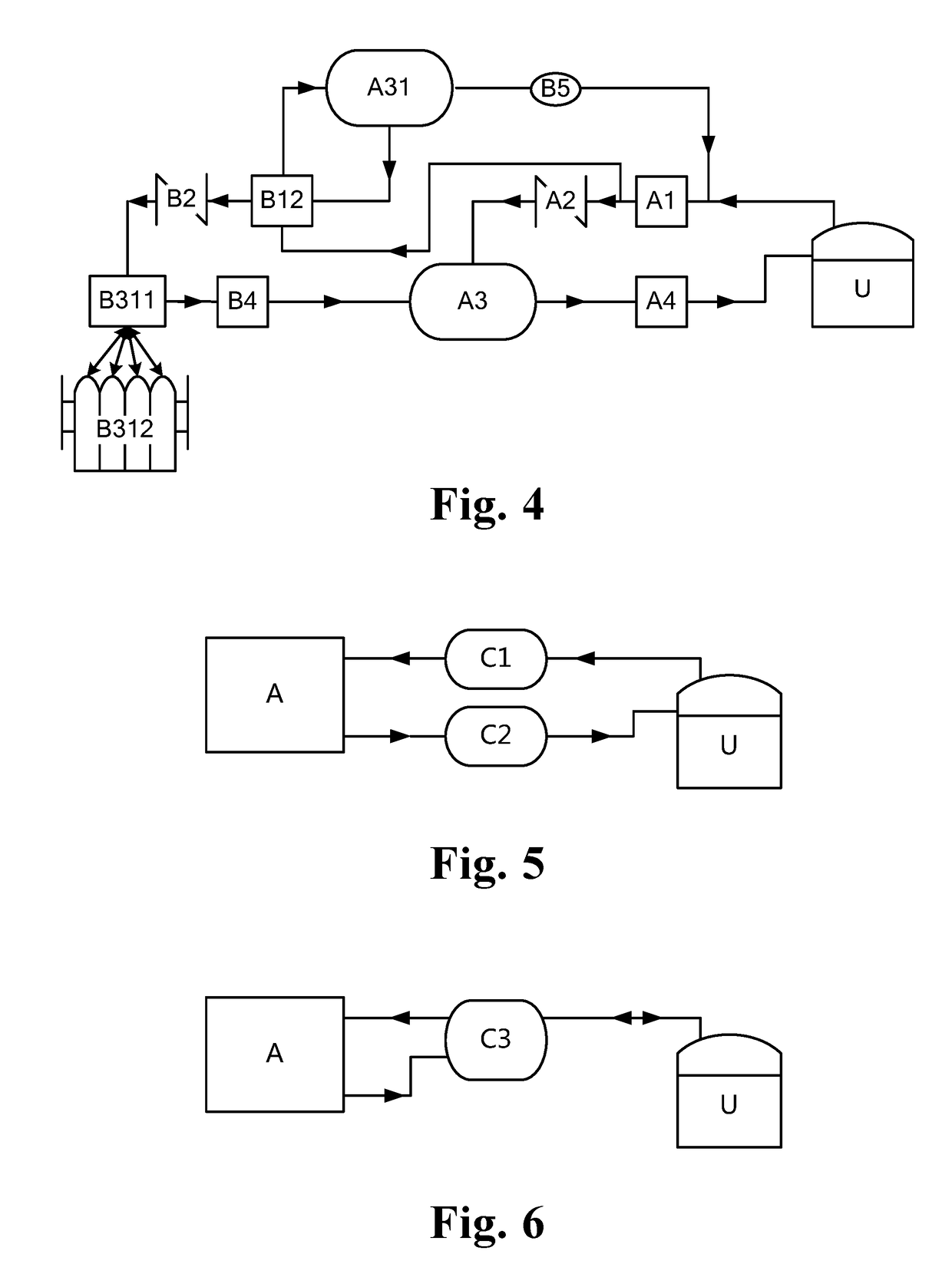
[0129]FIG. 4 is a schematic diagram of a cycle inert sealing system according to the present invention. Compared with the previous embodiment of the circulation inerting system including the gas source turnover unit, the rotation container B3 of the gas source servo device in this embodiment is a quick loading cylinder group. Each cylinder B312 in the quick cylinder group is provided with a charging and discharging assembly, and the gas source turnover unit further includes a charging and discharging assembly unit B311 having a gas input interface, a degassing output interface and a cylinder interface, Blowout assembly B311 to the gas input interface connected to the filling check valve B2 gas output side, gas output interface connected to the gas valve control assembly B4 gas input side, the cylinder interface with each cylinder B312 charge and discharge Components connected and two-way valve control connectivity.

[0130]Cylinders with quick-loading cylinder group can be replaced, su...


PUM


Abstract

A circulating inset-gas seal system based on gas-supply servo device and QHSE based storage and transportation method are provided. The gas-supply servo device includes a servo constant pressure unit including: inlet gas compressors a charging check valve, a gas supply container and a degassing valve control unit which are connected in sequence and communicated and controlled by a one-way valve. According to a preset gas pressure of the gas phase space in the material container, a inert sealing medium filled in the material container group is received, stored and released via an inerting pipe to form a station-type circulating inert seal system. A multi-group circulating inerting system cooperates with a mobile material container for self-sealing loading and unloading, which is capable of realizing a QHSE storage and transportation system with no gas phase emission.

Description

CROSS REFERENCE OF RELATED APPLICATION[0001]The present application claims priority under 35 U.S.C. 119(a-d) to CN 201710187784.7, filed Mar. 27, 2017.BACKGROUND OF THE PRESENT INVENTIONField of Invention[0002]The present invention relates to the field of the storage and transportation technique of the liquid hazardous chemicals in bulk, and more particularly to the field of autonomous defense technique for military oil supply projects. Specifically, the present invention relates to a gas-supply servo device, a circulating inert-gas seal system based on the gas-supply servo device and an integrated storage and transportation method based on the quality, health, safety and environmental (QHSE) of the system.Description of Related Arts[0003]Materials with strategic resource attributes, such as oil and its products, are both a support for national strength and a component for combat power. As such materials and their storage and transportation methods, engineering facilities and techni...

Claims


Application Information

Patent Timeline
Patent Type & Authority Applications(United States)
IPC IPC(8): F17D1/05F17D3/01F17D1/07F17D5/00F17C5/06F17C13/04F17C13/02
CPCF17C2223/0123F17C2250/043F17D1/05F17D3/01F17D1/07F17D5/005F17C5/06F17C13/04F17C13/025F17C2221/033F17D1/04A62C3/065A62C99/0018
Inventor SUN, QIANGDANMU, YUNTAO
Owner SUN QIANGDAN
Why Eureka
Try Eureka