
Method for Stabilizing Atomic Devices

a technology of atomic devices and stabilization methods, which is applied in the direction of laser details, laser output parameters control, semiconductor lasers, etc., can solve the problems of insufficient laser output power, limited tuning range available, and change the output power of lasers, etc., to achieve high dynamic range, high bandwidth, and high bandwidth

Active Publication Date: 2018-08-02
QUSPIN
View PDF10 Cites 35 Cited by
  • Summary
  • Abstract
  • Description
  • Claims
  • Application Information

AI Technical Summary

Benefits of technology

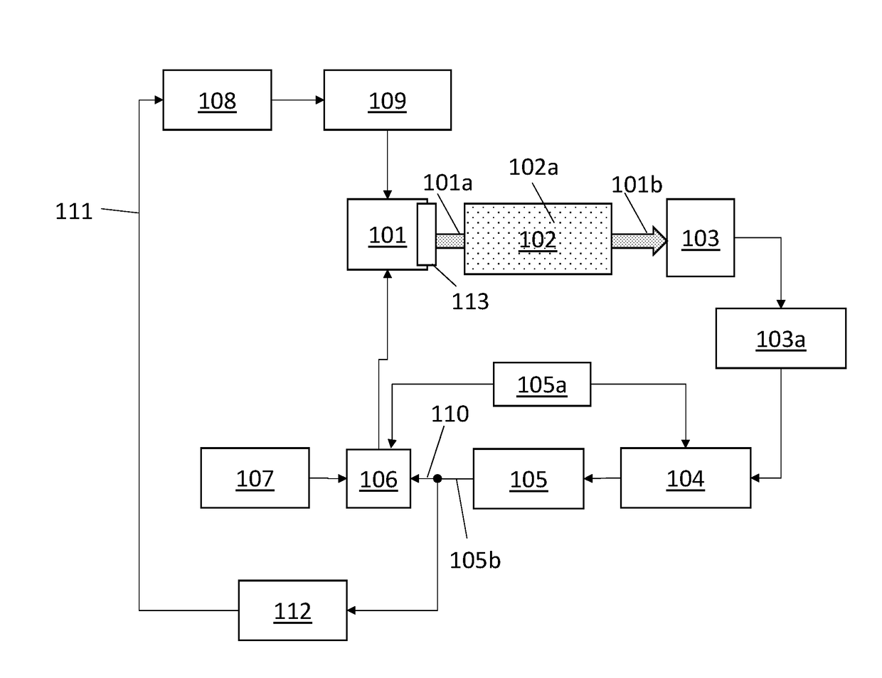
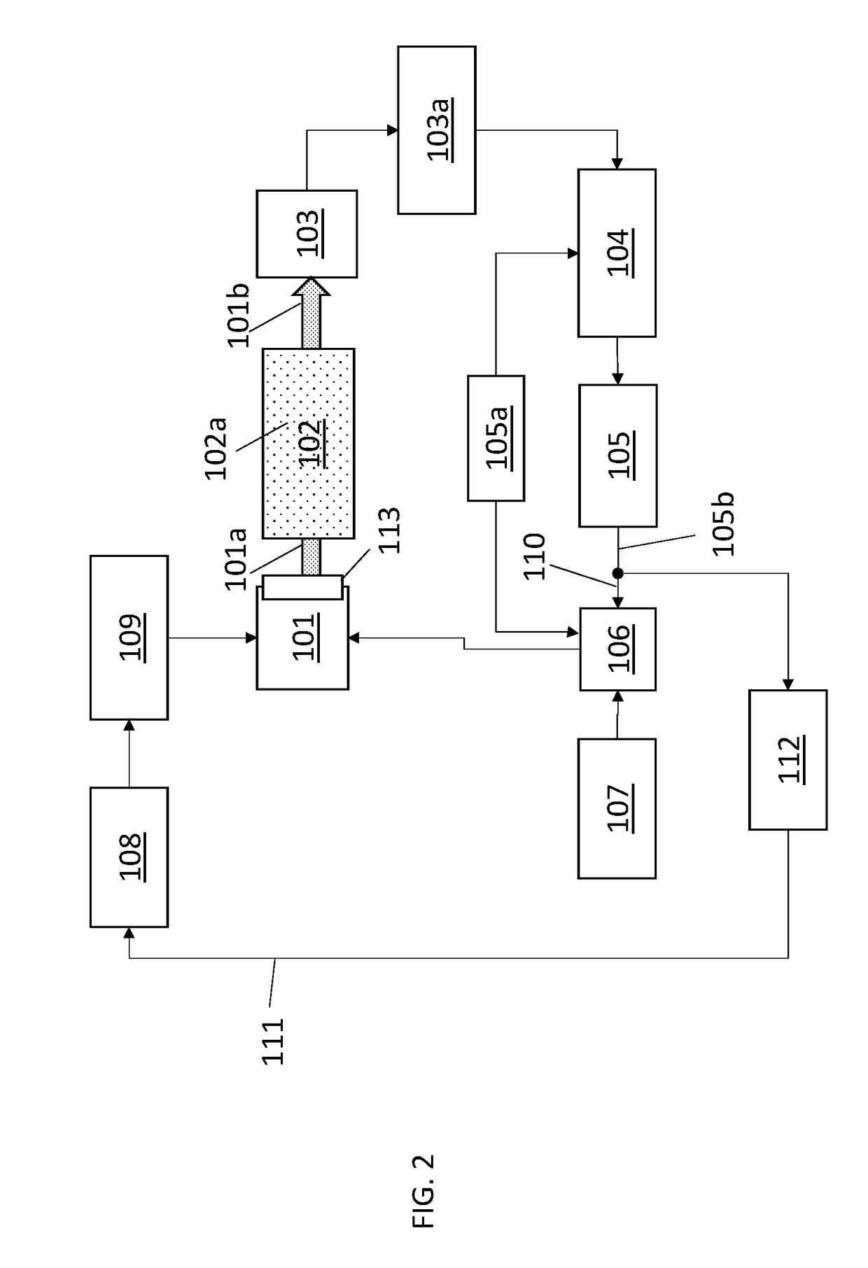
The present invention is a system and method that combines two laser parameters to achieve high bandwidth and high dynamic range. The first parameter, such as the laser injection current, is locked to the atomic resonance to achieve high bandwidth. The second parameter, such as the laser temperature, is stabilized simultaneously to cancel out the hump in the temperature lock. This two-stage locking system achieves both high bandwidth and high dynamic range without the need for an external temperature sensor and removes the response hump resulting from the slower temperature lock.

Problems solved by technology

The downside of this approach is that only a limited tuning range is available to keep the laser wavelength locked with the laser injection current alone.
If the diode laser temperature changes by more than one or two degrees, there may not be sufficient range to keep the laser wavelength locked to the resonance by changing the injection current.
In addition, changes or fluctuations in the laser diode temperature when compensated by changing the injection current, changes the output power of the laser.
Fluctuating optical power negatively affects the stability of the OPA device.
However, the downside of this approach is that depending on how the laser diode is mounted on a substrate, the thermal time constant of the laser diode heater can be very long, thereby decreasing the lock bandwidth.
If the wavelength is ‘tightly’ locked with temperature, the lock can induce a response ‘peaking’ or ‘hump’ at the frequency of the lock bandwidth, which is often unacceptable.
If the feedback loop is too loose, it can lead to low frequency drift in the output wavelength which is also undesirable.

Method used


Image

  • Method for Stabilizing Atomic Devices
  • Method for Stabilizing Atomic Devices
  • Method for Stabilizing Atomic Devices

Examples


example 1

[0033]As an example, a rubidium optically-pumped atomic (OPA) device has been constructed. A schematic diagram of the OPA device is shown in FIG. 4. For purposes of illustration, the top box 301 encloses the sensor optical components. The bottom box 302 encloses modulator 120a, the PID servo controller 120 and a second PID servo controller 160. A laser diode 10, such as a vertical cavity surface emitting laser, was mounted on a baseplate with a small resistive electrical heater 180 placed in close proximity to the laser diode 10. The light beam 20 was collimated by an optical lens 30, and the polarization of the light was adjusted for optimal performance of the OPA device with a waveplate 50. The intensity of the was also adjusted for optimal performance of the OPA device with an absorptive filter 40. The laser light was directed towards a sealed, transparent glass vessel or vapor cell 70 containing a vapor of rubidium metal 60. The rubidium vapor cell 70 was placed inside an oven 7...

example 2

[0038]The above example described how the present invention was used as a laser wavelength reference for atomic devices. In this embodiment, the system stabilizes the laser wavelength to an optical cavity instead of an atomic vapor. These systems often require a fast feedback loop, since the cavity has a very narrow linewidth and larger drift compared to many atomic resonances. However, several lasers can be used, such as but not limited to Fabry-Perot lasers, vertical-cavity surface-emitting lasers, distributed feedback lasers, and distributed Bragg reflector lasers.

[0039]When the laser is frequency-locked to the side of a cavity fringe, the actual output frequency can change when the laser power fluctuates and therefore it is important to keep the laser power constant as well. For example, a Fabry-Perot laser may be locked to the side of a cavity fringe. The laser frequency can be tuned fast over small discursions with the laser injection current and slowly over a wide range of fr...

example 3

[0041]The above described system and method may be used to stabilize a magnetic field in space using electromagnetic coils with high bandwidth as well as with a large dynamic range. The dynamic range refers to the maximum magnitude of the field that the electromagnetic coil system can generate, and bandwidth relates to the maximum rate at which the electromagnetic coils can respond. A magnetic sensor may be used to measure the original magnetic field in the region of interest. If the original field is high or low compared to a desired value, the electromagnetic coils can be energized appropriately to adjust the field value to the desired level. Thus, an electronic feedback loop can be established using the magnetic sensor and electromagnetic coil system to lock the magnetic field to a desired value in a region around the sensor.

[0042]To achieve a large dynamic range, an electromagnetic coil with a large number of turns can be utilized. However, coils with large number of turns have ...


PUM


Abstract

A two-stage laser stabilization method is described to simultaneously servo two coupled laser parameters that control the wavelength of a laser, such as the laser injection current and the laser temperature, in order to simultaneously stabilize the laser frequency and output power. Two error signals are generated by passing the laser light through a frequency discriminator, such as an atomic resonance, to generate two control loops for the two coupled laser parameters. A primary control loop servos the faster laser parameter, such as the laser injection current, by direct use of the error signal. A secondary slower control loop ensures that this said error signal will remain at zero, by controlling the second laser parameter, such as the laser temperature.

Description

[0001]The following application is an application for patent under 35 USC 111 (a). This invention was made with government support under HD074495 awarded by the National Institutes of Health. The government has certain rights in the invention.FIELD OF INVENTION[0002]This disclosure relates to the field of laser wavelength stabilization, specifically a system and method thereof.BACKGROUND[0003]Optically pumped atomic (OPA) devices, developed in mid-1950's, such as atomic clocks, atomic magnetometers, and atomic gyroscopes, are used in a number of scientific and advanced technology applications. The light source used for optical pumping in these OPA devices was originally a gas discharge lamp. In recent years, semiconductor lasers have become available with sufficient performance to replace the gas discharge lamps used in the conventional OPA devices. The benefits of using a laser instead of a discharge lamp include substantial reduction in size and electrical power consumption, poten...

Claims


Application Information

Patent Timeline
IPC IPC(8): H01S5/0683H01S5/06G01R33/26
CPCH01S5/0683G01R33/26H01S5/0612H01S3/1303H01S5/06808H01S5/06837H01S5/0687
Inventor SHAH, VISHAL
Owner QUSPIN
Learn More