
Method for preparing patterned coverlay on substrate

a technology of patterned coverlay and substrate, which is applied in the direction of film/foil adhesives, synthetic resin layered products, solid-state devices, etc., can solve the problems of reducing the toughness of the coverlay, and increasing so as to and reduce the thickness of the coverlay. , the effect of low warpag

Active Publication Date: 2018-10-04
ETERNAL MATERIALS CO LTD
View PDF5 Cites 6 Cited by
  • Summary
  • Abstract
  • Description
  • Claims
  • Application Information

AI Technical Summary

Benefits of technology

The present invention provides a method for making a polyimide dry film without the need for complex steps like exposure and development. The film is adhesive-free and does not require an adhesive, reducing thickness and warping of the product. The method is cost-effective and simple. The polyimide dry film has excellent adhesion to flexible boards and is heat-resistant and bendable.

Problems solved by technology

Since the polyimide film needs to be stretched during its preparation process, the thickness thereof cannot be too thin; otherwise, the toughness would be greatly reduced and the stretch would be poor.
Further, since the adhesion between the polyimide film and the flexible copper clad laminate that is commonly used as the flexible plate 50 is poor, an adhesive such as epoxy or acrylic adhesive needs to be used, which also increases the thickness of the coverlay.
Therefore, a traditional coverlay is relatively thick (generally greater than 20 μm), which does not meet the current process requirements of being light and thin.
However, compared with polyimides, the epoxy resins in the adhesive layer have poor heat resistance and bendability.
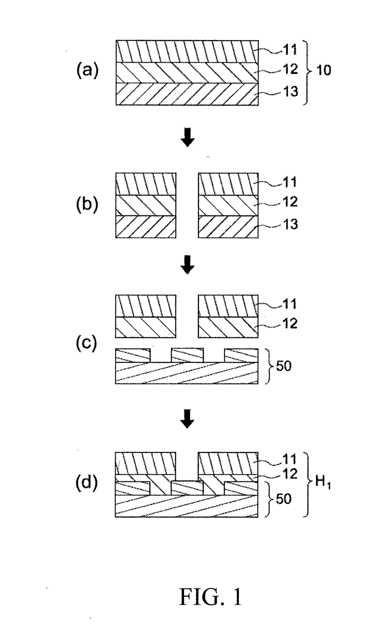
In the above method, since it is necessary to use an adhesive with strong adhesion, the adhesive is difficult to dissolve and remove when an alignment error occurs, and reprocessing cannot be performed.
In addition, due to the difference between the coefficients of thermal expansion between the adhesive layer, the insulating material layer and the flexible board, warpage is problematic.
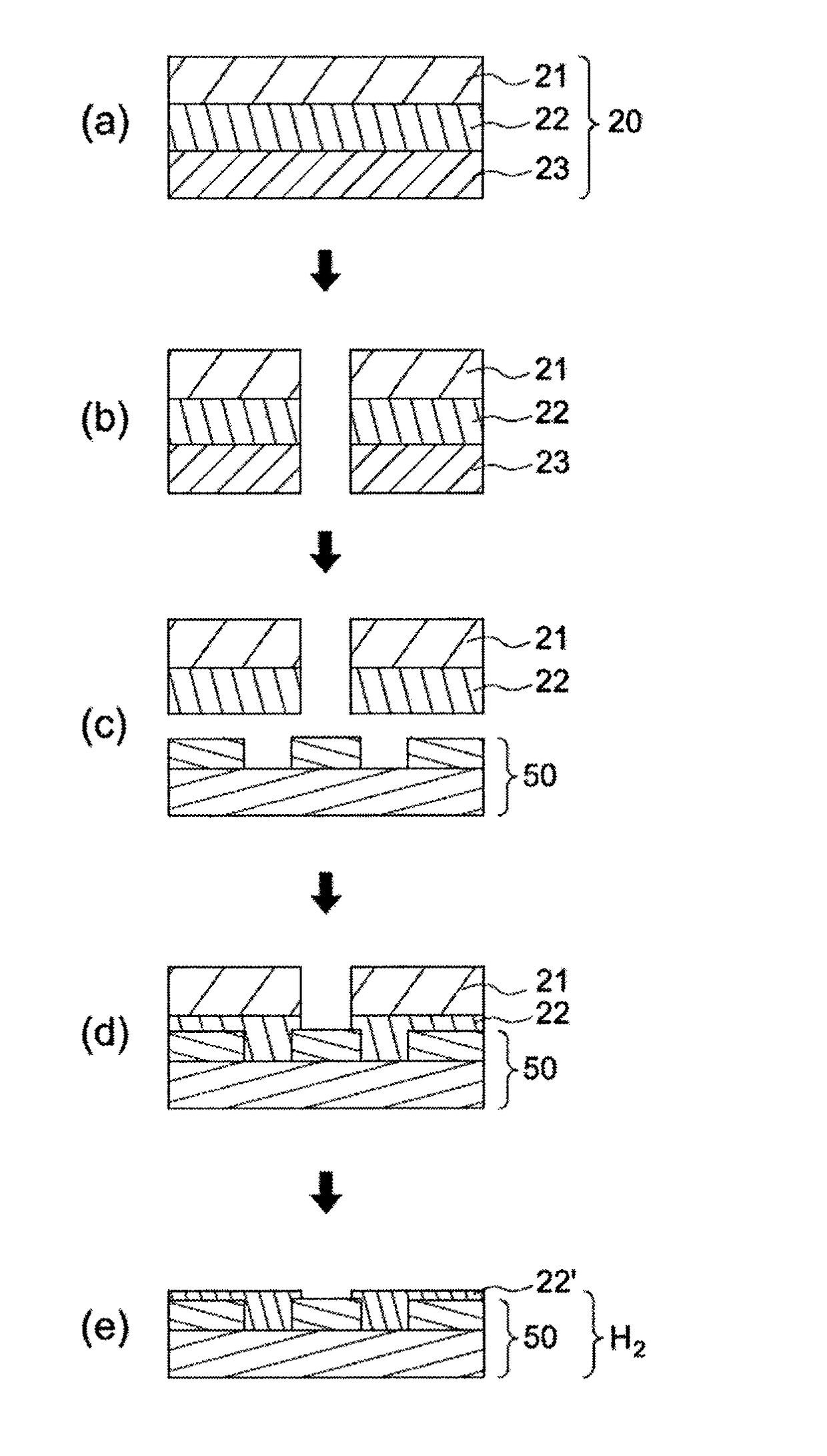
Moreover, to enable the adhesive layer to have a desirable flowability, the lamination step (d) in FIG. 1 generally takes place under high temperature and high pressure conditions, for example, under a pressure of 85-100 kg / cm2 and at a temperature of 150-190° C. However, in this case it is likely to have a problem of glue overflow (glue bleeding).
Another common problem is that when the film is laminated onto the patterned surface, there may be unwanted gas remaining therebetween, which will affect the reliability and quality of the final product.
However, in most cases, the method that uses the vacuum lamination apparatus can only achieve lamination in a single-sheet manner, i.e., a sheet by sheet manner.
The method that uses the vacuum lamination apparatus is time-consuming, fails to satisfy the objectives of a continuous process and rapid production, and is not cost-efficient due to the high cost of the apparatus

Method used


Image

  • Method for preparing patterned coverlay on substrate
  • Method for preparing patterned coverlay on substrate
  • Method for preparing patterned coverlay on substrate

Examples


preparation example

[0149]1. Synthesis of Non-Photosensitive Polyimide Precursor Resin PAA-1

[0150]15.23 (0.052 mol) 4,4′-Biphthalic dianhydride (referred to hereinafter as BPDA) was dissolved in 100 g N-methyl-2-pyrrolidone (referred to hereinafter as NMP) and 0.959 g (0.013 mol) n-butanol and 0.48 g (0.006 mol) 1-methylimidazole were added dropwise. The solution was stirred at a fixed temperature of 60° C. for 2 hrs to carrying out the reaction. 82.88 g (0.259 mol) 2,2′-bis(trifluoromethyl) benzidine and 300 g NMP were added to the solution at 10° C., stirred for 0.5 hr, and then 60.92 g (0.207 mol) BPDA and 200 g NMP were added and stirred at 10° C. After 4 hrs, the temperature was increased to 60° C. and the reaction was carried out for 8 hrs with stirring. Finally, 0.83 g (0.006 mol) ethyl trifluoroacetate was added and stirred for 1 hr. Then, 0.22 g 5-aminotetrazole and 24 g NMP were added at room temperature and stirred for 1 hr, to obtain a polyimide precursor resin PAA-1 having a solid content ...

example 1

ation

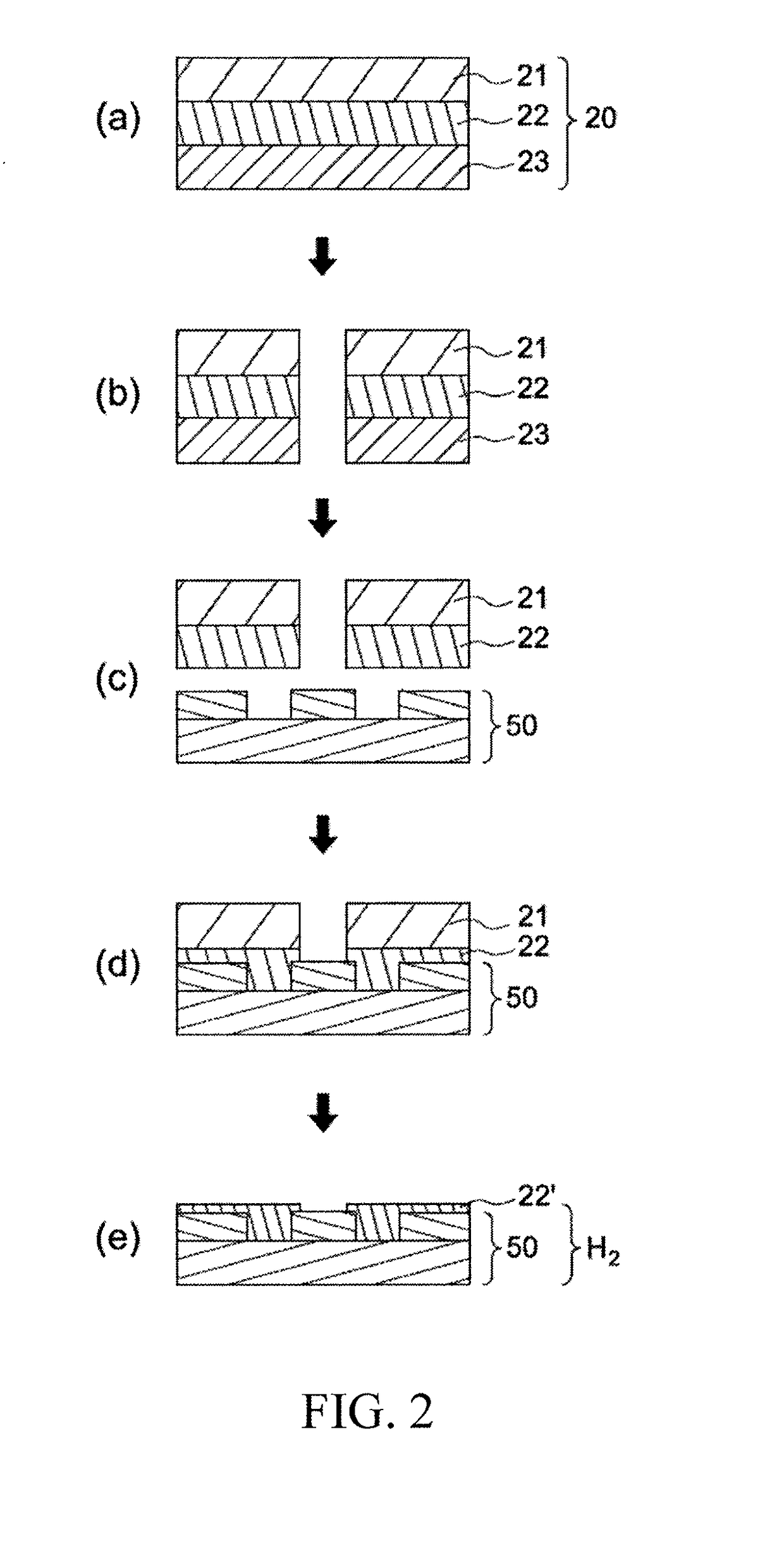
[0153]A 20*20 cm sheet was taken from the dry film prepared in the preparation example and a round hole of ¼″ (that is, about 6.35 mm in diameter) was punched out of the sheet by using a mechanical punching machine, and then the release film was removed.

[0154]A 20*20 cm copper clad laminate (L / S=30 / 30 μm; L / S=line width / line spacing; thickness 12.7 μm) on which a circuit was fabricated was provided. Deionized water was applied onto the surface (which has a circuit formed thereon) of the copper clad laminate, and the sheet was adhered to the copper clad laminate using hot rollers at a temperature of 80° C. and under a pressure of 5 kg / cm2 in such a manner that the polyimide precursor layer faces the surface of the copper clad laminate having the circuit. The PET film was peeled off, and then the sample was placed in a nitrogen oven, and baked by heating for 1 hr at 170° C. and then for 2 hrs at 350° C., to prepare a circuit board FPC-1 with patterned polyimide coverlay.

example 2

ation

[0155]The method is the same as that in Example 1, except that no deionized water was applied onto the surface (which has a circuit formed thereon) of the copper clad laminate. A circuit board FPC-2 with patterned polyimide coverlay was prepared.


PUM

PropertyMeasurementUnit
Thicknessaaaaaaaaaa
Thicknessaaaaaaaaaa
Flexibilityaaaaaaaaaa

Abstract

The present invention relates to a method for preparing a patterned polyimide coverlay on a substrate. The method includes: providing a polyimide dry film including a carrier and a non-photosensitive polyimide layer on the carrier, the non-photosensitive polyimide layer containing (i) a polyimide precursor or soluble polyimide and (ii) a solvent; forming a predetermined pattern in the polyimide dry film; laminating the patterned polyimide dry film onto a substrate in such a manner that the non-photosensitive polyimide layer faces the substrate; and forming a patterned polyimide coverlay by heating.

Description

BACKGROUND OF THE INVENTION1. Field of the Invention[0001]The present invention relates to a method for preparing a patterned coverlay on a substrate, and particularly to a method for preparing a patterned coverlay on a flexible printed circuit board.2. Description of the Related Art[0002]In recent years, it has been emphasized that electronic products should be lighter, thinner, shorter or smaller, and thus the size of various electronic parts and components has to be reduced accordingly. Under such a trend, there is greater incentive to develop a flexible printed circuit (FPC) board that is light and thin, has high temperature resistance and other characteristics and may be mass produced. Flexible printed circuit boards may be found in various electronic products that are currently popular, such as mobile phones, liquid crystal displays, and organic light-emitting diodes. A flexible printed circuit board is produced by arranging circuits and other electronic components on a flexib...

Claims


Application Information

Patent Timeline
IPC IPC(8): C09D179/08C08G73/10C09J7/02H01L27/32C08G73/14C08L63/00
CPCC09D179/08C08G73/1003C08G73/1039C09J7/0242C09J2479/086C08G73/14C08L63/00B29K2079/08H01L27/3241H05K3/281H05K2203/0537H05K3/0064C09J7/35C09J2203/326C09J2479/08C08G73/1067H05K1/0393H05K3/007H05K2201/0154H05K2203/0156H05K2203/016H01L21/02118H01L21/0274H01L21/3213C08G73/1032B32B27/281H10K59/10
Inventor CHENG, CHUNG-KAIWU, CHUNG-JENCHOU, MENG-YENHO, CHANG-HONGHUANG, PO-YUCHIANG, SHUN-JEN
Owner ETERNAL MATERIALS CO LTD
Learn More