Heat treatment method

a heat treatment method and component technology, applied in mechanical equipment, additive manufacturing, turbines, etc., can solve the problems of inability to heat treatment, and inability to meet the requirements of heat treatment, so as to reduce stress assisted oxidation, and reduce the scrap rate of components

Inactive Publication Date: 2018-12-20
ROLLS ROYCE PLC
View PDF7 Cites 0 Cited by
  • Summary
  • Abstract
  • Description
  • Claims
  • Application Information

AI Technical Summary

Benefits of technology

[0012]By sealing at least part of the component (e.g. a part having high residual stress) within a foil envelope containing an inert gas, it is possible to reduce stress assisted oxidation and thus reduce cracking in the component. This, in turn, reduces component scrap rate. The method does not require a further complex component processing step and allows increased design freedom as geometries which induce highly stressed locations need not be avoided provided that they are wrapped and sealed within the foil envelope. Furthermore, the method is economically viable since foil for forming the envelope may be obtained easily and cheaply from commercially available sources.
[0013]The foil envelope encloses the component / component part within a reduced volume (compared to the heat treatment vessel) which can be more effectively purged with inert gas thus reducing the exposure of the highly stressed location to residual oxygen contained within the heat treatment vessel.
[0020]When the second material (forming the foil envelope) is more susceptible to oxidation than the first material (forming the component), any oxygen remaining in the heat treatment vessel (or contained within the inert gas), preferentially oxidizes the envelope foil rather than the first material forming the component. In effect, in this embodiment, the foil envelope acts not only as a barrier but is also sacrificed to improve the purity of the inert gas surrounding the envelope and which may gain access to the component / combustor tile.
[0023]In some embodiments, the method further comprises grit blasting, surface finished or peening the surface of the component / combustor tile prior to enclosing it in the foil envelope. This removes surface irregularities and may further assist in crack reductions during heat treatment.
[0026]In some embodiments, the method comprises forming a spacing structure surrounding the component / component part (e.g. combustor tile) prior to enclosing it in the foil envelope. In this way, the foil envelope can abut the spacing structure, the spacing structure spacing the foil envelope from the component / component part (so that the foil envelope does not touch the component / component part / combustor tile).

Problems solved by technology

The resulting component often comprises defects such as cracks, porosity and layering defects.
It has been found that when the ALM component is formed of certain alloys e.g. high gamma prime (y′) nickel superalloys, the HIP or other heat treatment can result in unacceptable levels of cracking.
It is believed that this cracking is the result of low amounts of oxygen present in the argon (or other inert gas) causing stress assisted oxidation at highly stressed locations on the component.
In addition to high cooling rates, this results in highly stressed locations.
Under the influence of high residual stress and applied temperature the residual oxygen can diffuse into the component to form a brittle oxide which is then susceptible to cracking.
Attempts to eliminate the low amounts of residual oxygen (either in the inert gas or in the canister / heat treatment vessel) have proved very costly and therefore commercially unviable.
Prior art methods such as that disclosed in US2014 / 0034626 have added attempted to introduce a compressive residual stress in the component part but this involves an additional process step and is unsuitable for thin walled components where the method of introducing compressive stress (e.g. peening, shot blasting) could lead to undesirable distortion.

Method used


Image

  • Heat treatment method
  • Heat treatment method

Examples


Embodiment Construction

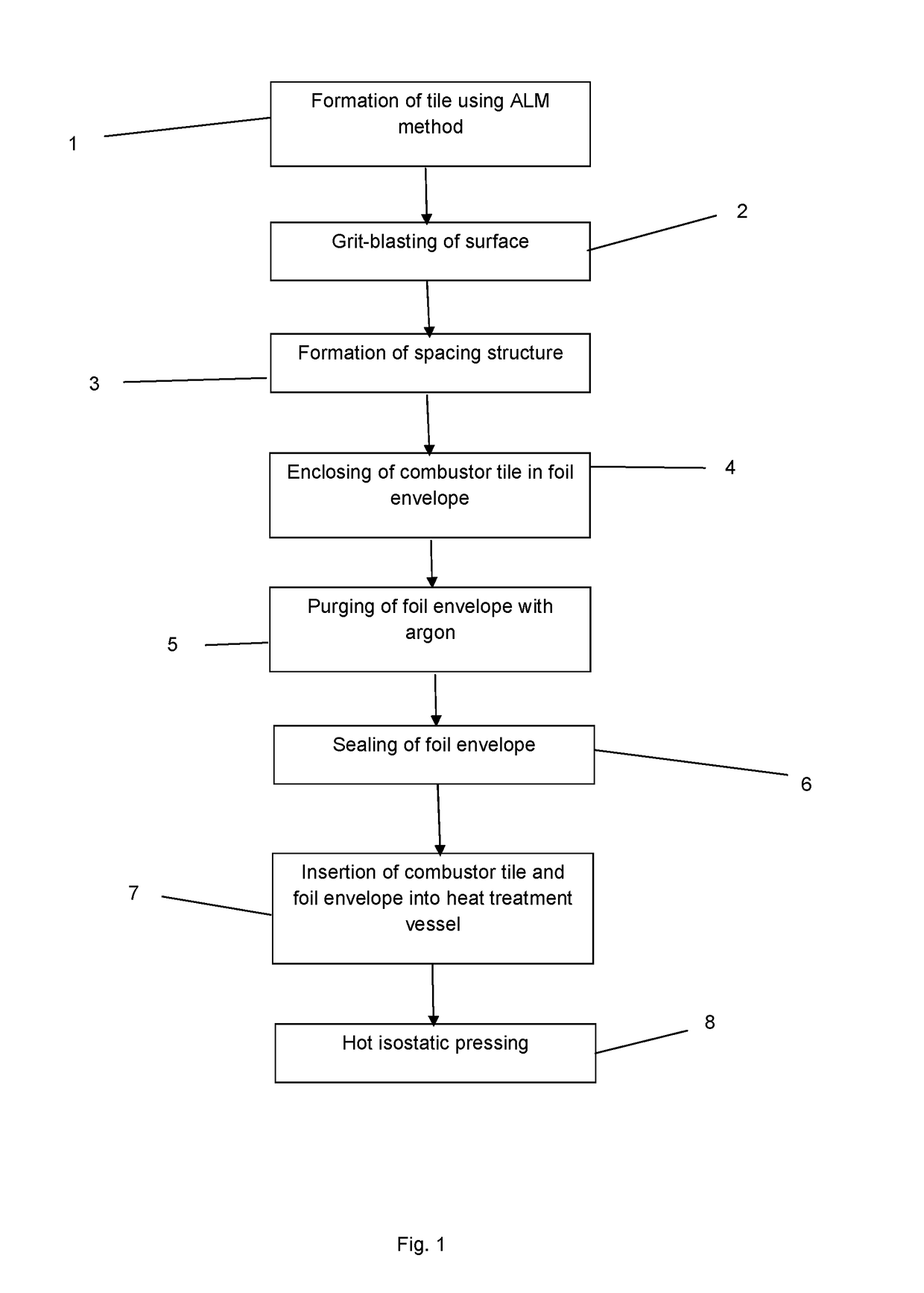
[0041]In step 1, a combustor tile is formed of a high gamma prime nickel superalloy CM247LC using an additive layer manufacturing method.

[0042]In step 2, the surface of the combustor file is grit-blasted to remove any surface irregularities.

[0043]In step 3, a spacing structure is formed to surround the combustor tile. The spacing structure comprises a plurality of struts which project from the combustor tile.

[0044]In step 4, the combustor tile is enclosed in a foil envelope formed of 0.05 mm thick 321 stainless steel foil. The foil is wrapped around the spacing structure such that the plurality of struts maintains a small spacing between the foil envelope and the combustor tile i.e. so that the foil envelope does not touch the combustor tile at any point. The foil envelope has an inlet opening at an uppermost edge and an outlet opening at a lowermost edge.

[0045]In step 5, the foil envelope is purged with argon by flowing argon into the inlet opening such that it passes through the f...


PUM

PropertyMeasurementUnit
isostatic pressureaaaaaaaaaa
pressuresaaaaaaaaaa
thicknessaaaaaaaaaa

Abstract

The present disclosure relates to a method of heat treating a component (e.g. a combustor tile) which may be formed of a first material e.g. a nickel superalloy. The component may be formed using an ALM method. The method comprises enclosing at least part of the component in a foil envelope which may be formed of a second material wherein the second material (e.g. stainless steel) is more susceptible to reactive oxidation than the first material. Next the envelope is purged with an inert gas (e.g. argon) and the envelope is sealed. The component is then heated e.g. using hot isostatic pressing.

Description

CROSS-REFERENCE TO RELATED APPLICATIONS[0001]This specification is based upon and claims the benefit of priority from UK Patent Application Number GB1707895.7 filed on 17 May 2017, the entire contents of which are incorporated herein by reference.BACKGROUNDField[0002]The present disclosure relates to a method of heat treating a component e.g. a component formed from additive layer manufacturing.Description of the Related Art[0003]In the aerospace industry, components such as combustor and turbine components manufactured by additive layer manufacturing (ALM) methods can have significant performance and weight advantages over components manufactured by more traditional methods.[0004]Powder bed ALM methods construct components layer by layer by depositing powder on a machine bed or base / build plate and then selectively consolidating or fusing the powder using an energy beam such as a laser or an electron beam. The powder deposition / consolidation steps are repeated to produce a three di...

Claims


Application Information

Patent Timeline
Patent Type & Authority Applications(United States)
IPC IPC(8): B22F3/15C22F1/10B22F3/24B22F3/12B22F5/00B33Y80/00
CPCB22F3/15C22F1/10B22F3/24B22F3/1216B22F5/009B33Y80/00B22F3/1055B22F2003/248B22F2003/247B22F2301/15B33Y10/00B22F3/1208B22F2998/10Y02P10/25B22F10/64B22F10/66B22F10/28B33Y40/20B22F10/20
Inventor PARDHI, YOGIRAJ
Owner ROLLS ROYCE PLC
Why Eureka
Try Eureka