
Production Method and Production Device for Nitrogen Compound

a production method and nitrogen compound technology, applied in the direction of solid-state diffusion coating, crystal growth process, polycrystalline material growth, etc., can solve the problem of difficult to obtain the optimal crystal growth condition, the theoretical limit of the luminous efficiency of led alone is about 270 lm/w, etc., to achieve excellent properties, save power consumption, and save weight

Inactive Publication Date: 2019-05-23
NAT INST OF ADVANCED IND SCI & TECH
View PDF16 Cites 0 Cited by
  • Summary
  • Abstract
  • Description
  • Claims
  • Application Information

AI Technical Summary

Benefits of technology

This patent presents a remote-type method for generating a nitriding plasma using a strong electric field to transform nitrogen-based gas into a plasma state and irradiate a base material with high-density nitrogen-based reactive species. The method can be performed at low temperatures and without the need for direct voltage application to the nitriding target, resulting in improved efficiency and reduced power consumption. The nitriding treatment can also lead to the formation of high-quality nitride films with excellent properties such as hardness. The method can be used for the low-temperature growing of nitrogen compounds, such as InGaN nitride, which is crucial for the production of green LEDs.

Problems solved by technology

In this case, the theoretical limit of the luminous efficiency of the LED alone is about 270 lm / W.
The problem is to improve the external quantum efficiency of a green LED formed of, as a light-emitting material, InGaN in which In accounts for about 30%.
The reason for this is that it is desirable to grow In, which is a constituting element of green LEDs, at a low temperature of about 600 degrees C. because In has a high vapor pressure, whereas for nitrogen (N), it is necessary to decompose ammonia at a high temperature of 800 degrees C. or higher, or desirably 1,000 degrees C. or higher to supply nitrogen in an active state, making it difficult to obtain an optimum crystal growth condition.

Method used


Image

  • Production Method and Production Device for Nitrogen Compound
  • Production Method and Production Device for Nitrogen Compound
  • Production Method and Production Device for Nitrogen Compound

Examples


embodiment 1

[0105]In the present embodiment, a titanium metal was used as a base material, and a microwave plasma generating apparatus capable of generating a plasma having a jetting type shape was set in the chamber, to perform nitriding of the surface of the base material at a pressure of 1 kPa or higher. The nitriding method used in the present embodiment will be described below in detail.

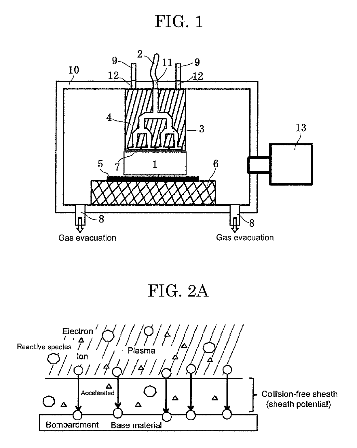
[0106]In the present embodiment, the apparatus illustrated in FIG. 1 is used. The microwave plasma generating apparatus is disposed in the chamber (10) formed of a metal. The nozzle (7) is a linear rectangular nozzle provided at one end surface of the dielectric substrate (4). The nozzle (7) has a slit shape in order to enable wide, uniform jetting of a plasma generated by application of a microwave, together with a material gas.

[0107]In the present embodiment, a method for protecting the plasma source from the radiant heat mentioned above is employed. In the present embodiment, as a cooling method, the pla...

example 1

[0108]One Example of the present embodiment was worked with the use of nozzle having a slit shape and a cross-section having a width of 50 mm and a clearance of 0.5 mm. In the chamber (10), a titanium base material (5) having a thickness of 1 mm and a size of 25 mm×25 mm was set immediately below the nozzle (7) of the microwave plasma generating apparatus in a manner that the width of the nozzle was aligned in the longer direction of the base material, and a plasma CVD treatment was applied to the titanium base material. The procedures for the treatment were as follows.

[0109]The titanium base material (5) was set on a base material table (6) provided in the chamber (10). The height of the base material table (6) was adjusted such that the distance between the nozzle (7) and the titanium base material (5) would be 3 mm. Next, the chamber (10) was evacuated through the gas evacuation pipe (8).

[0110]Next, a nitrogen gas was introduced at a rate of 2 L / min into the chamber (10) through ...

example 2

[0116]As one Example of the present embodiment, a nitriding treatment was applied on a titanium base material with the same apparatus as in Example 1.

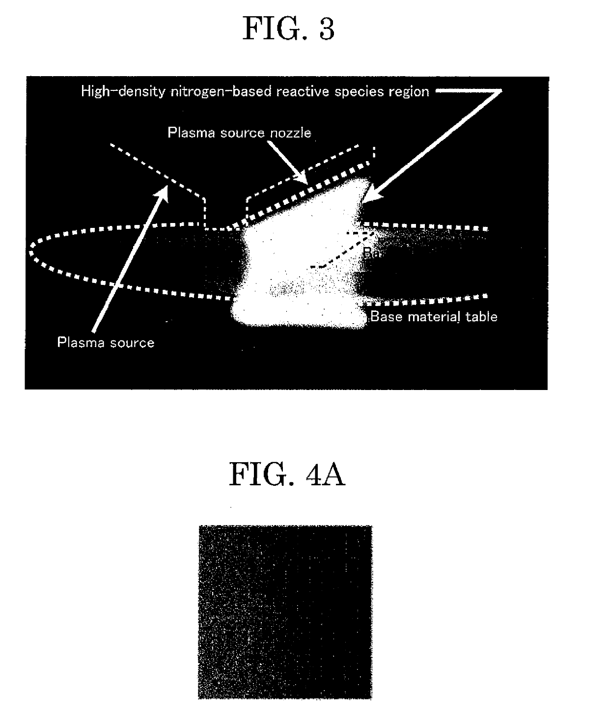
[0117]FIG. 4A and FIG. 4B illustrate photographic images of the titanium surface before and after the nitriding treatment, respectively. It can be seen that the titanium surface became golden and was uniformly treated through the nitriding treatment. Here, having become golden means having been nitrided. Conditions for generation in the present Example include a microwave power of 100 watts, a gas pressure of 2.66 kPa, a nitrogen gas flow rate of 1 L / min, a treatment time of 1 hour, the temperature of the base material table on which the base material was set of 800 degrees C., and a distance of 3 mm between the nozzle (7) and the titanium base material (5).

[0118]FIG. 5 plots measurement results of Raman spectroscopic spectra of the nitride layer obtained in the present Example, where the spectra were measured with a microscopic Raman ...


PUM

PropertyMeasurementUnit
Pressureaaaaaaaaaa
Angleaaaaaaaaaa
Poweraaaaaaaaaa

Abstract

To provide a method and apparatus for production of a nitrogen compound film by a plasma, wherein the method and apparatus are suitable for area enlargement by a process at a higher pressure with lower power consumption, without applying a voltage to a base material, and without using a large chamber. In nitrogen compound production for producing a nitrogen compound by generating a microwave plasma, in a step of jetting a material gas containing a nitrogen-based gas onto a surface of a base material from a nozzle under flow rate control while applying a microwave to the material gas to thereby irradiate the surface of the base material with a plasma containing nitrogen-based reactive species generated from the material gas, the pressure is set higher than a pressure at which the mean free path of ions in the plasma is shorter than the Debye length.

Description

TECHNICAL FIELD[0001]The present invention relates to a producing method and a producing apparatus for a nitrogen compound using a microwave plasma source.BACKGROUND ART[0002]Hitherto, as a method for producing a thin film of a nitrogen compound, there have been known, for example, a method of applying a nitriding treatment to a surface of a base material and a method of forming a nitrogen compound on a surface of a base material by a thin film forming technique.[0003]The nitriding treatment method is one of surface modification treatment methods, and is widely used as a surface modification method for nitriding surfaces of, for example, iron and steel, and titanium. Products to which nitriding surface treatment is applied are used in, for example, machine tool parts such as spindles and. gears, internal-combustion engine parts such as turbines and fuel injection nozzles, reduction gears of, for example, power shovels, and aircraft and automobile parts. Further, in recent years, dev...

Claims


Application Information

Patent Timeline
IPC IPC(8): C30B29/38C23C16/511H01L33/00C23C16/34C30B25/16H01J37/32
CPCC30B29/38C23C16/511H01L33/005C23C16/34C30B25/165H01J37/32201C23C8/36C30B25/18H05H1/30C23C16/303C23C16/4551C23C16/513C23C16/517C23C16/45578
Inventor ITAGAKI, HIROTOMOSAKAKITA, HAJIMEKIM, JAEHOOGURA, MUTSUOWANG, XUELUNHIROSE, SHINGO
Owner NAT INST OF ADVANCED IND SCI & TECH
Learn More