
Vertical take-off and landing aircraft

Active Publication Date: 2019-06-06
OBSHCHESTVO S OGRANICHENNOJ OTVETSTVENNOSTYU AVIANOVATSII
View PDF13 Cites 11 Cited by
  • Summary
  • Abstract
  • Description
  • Claims
  • Application Information

AI Technical Summary

Benefits of technology

The patent describes a small, mobile, environmentally friendly and safe multicopter vertical takeoff and landing (VTOL) aircraft that is easy to maintain, failsafe, cost-effective and space-saving. It can be used for personal transportation, flying crane, airdrop platform, reconnaissance and attack means, heavy unmanned aircraft or remotely-piloted aircraft. The aircraft has increased fail-safe, maintainability, and overall flight safety, as well as space-saving in both operational and folded condition.

Problems solved by technology

The disadvantage of the said flying vehicle is that its airframe is a flat-type beam and it does not provide sufficient structural rigidity which is necessary for the whole structure to be resistant to precision oscillation and nutation oscillation generated by heavy propellers.
This, in turn, causes resonance oscillation to appear and lead to fatigue defects of the airframe which makes the task of flight stabilization rather difficult.
If at least one propeller out of four fails (and any other structural elements associated with the functioning of the propellers), it causes the flying vehicle to crash, its parachute recovery system is unable to prevent the accident and only mitigates the consequences.
The efficiency of the parachute recovery system is doubtful for low flight altitudes.
Heavy propellers of large diameter cannot be stopped quickly in emergency.
The disadvantage of the said flying vehicle is that both of its propellers are driven from the same engine, a double-propeller layout is not so reliable, any engine failure or any malfunction of propellers, transmission, aerodynamic control surfaces or other related systems will cause spinning of the flying vehicle during the flight making it impossible for the pilot to escape and for the flying vehicle to be rescued.
Flat-type beam does not provide the structural rigidity necessary to withstand the precision and nutation oscillation generated by heavy propellers.
This causes the resonance oscillation to appear, as well as fatigue defects in the airframe which makes the task of flight stabilization rather difficult.
Heavy propellers of large diameter cannot be stopped quickly in emergency.
The disadvantage of the said vehicle is that it has a single fuel supply system and a fuel tank feeding all of the eight engines, so the failure of the fuel supply system would immediately cause all the engines to stop.
Autorotation landing is not possible for this vehicle because of smaller impellers and low deceleration force of the engines, therefore, flight safety by means of engine redundancy is not ensured.
The Wankel engines are known as rather complicated to control, because of higher acceleration time as compared with electric engines.
This add-on makes the flying vehicle heavier and less reliable, it also means more maintenance due to one more serviceable unit installed on each of the engines.
All those disadvantages of propulsion system cause the flying vehicle overswinging even in calm air (which is pretty well noticeable in the published videos where the tests of the flying vehicle are shown) which is likely to cause loss of hold during the flight and finally leads to the accident.
This change did not help to overcome the fire hazard issue, but negatively affected the power-to-weight ratio and engine acceleration time.
Among the disadvantages which prevented this invention to be launched into serial production were the following: low reliability, short service life and maintainability of the Wankel engines and propeller pitch control system, low producibility of the flying vehicle, clumsy design of the flying vehicle—bowl-shaped with high windage, lack of foldability features together with increased cost.
Among the disadvantage of the most similar product are: interdependent power system with all the engines supplied by the same battery and with extensive power wiring between the battery and the engines which does not ensure the flight safety via redundancy, because failure of the battery causes all of the engines to stop at the same time, while small diameter of propellers and low engine deceleration force make the autorotation landing impossible.
The fuselage design with fracture susceptible carbon members (with dia. over 10 meters) of the flat structural airframe where the propellers are installed make the flying vehicle heavier without solving any design task.
The combination of the above disadvantages increases the cost of the flying vehicle and has negative impact on its maintainability.
The efficiency of the parachute recovery system is doubtful for low flight altitudes.

Method used


Image

  • Vertical take-off and landing aircraft
  • Vertical take-off and landing aircraft
  • Vertical take-off and landing aircraft

Examples


embodiment 1

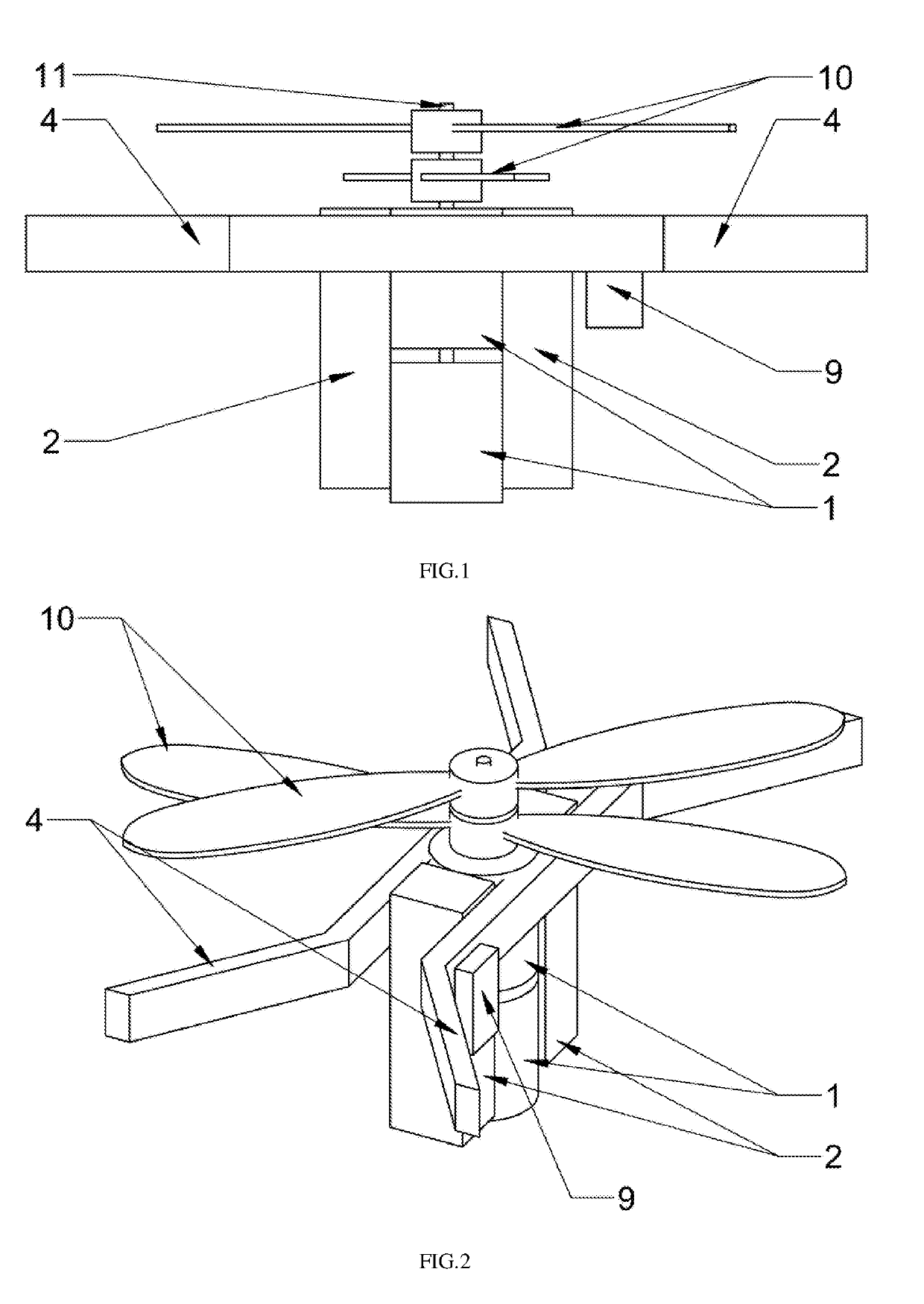
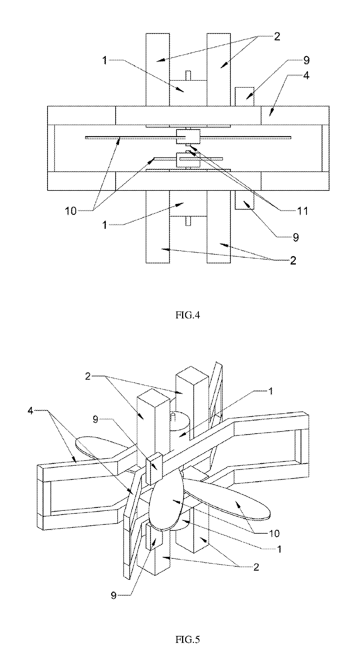
[0111]According to the embodiment 1, the engine unit comprises one or more electric engines arranged in-line, with horizontally rotating propellers. The engines are supplied from one power supply source or a group of power supply sources located directly on the engine support structures and located within an airstream produced the at least one horizontally rotatable propeller of this engine unit. Ancillary power supply sources located beyond the engine unit, may be used; they supply several engine units at once, all the engine units cannot be supplied from one power supply source. It is possible to install the ancillary power supply source inside the hollow airframe elements, in the unoccupied space between the propellers, above and under the engine units.

[0112]In one of the non-limiting embodiments of the present technology, installation of power supply source in the unoccupied space between the propellers of the section is used.

[0113]Each of the engine units comprises an individua...

embodiment 2

[0119]According to the embodiment 2, the engine unit (3) comprises one or more pneumatic engines, arranged in-line, with horizontally rotatable propellers (10) attached and downward exhaust pipe.

[0120]Each pneumatic engine is supplied from a compressor (8), installed in the central section of the flying vehicle, through the piping and system of electrically driven valves, regulating the flow of compressed gas to the pneumatic engines and receiving signals from the distributed control system via the onboard information network. The compressor (8) is a combustion engine or a turbocharged unit with the air compression system, supplied with the fuel from the tank located above the compressor and attached to the compressor body. For temporary redundancy the compressor may comprise a pneumatic accumulator attached to the compressor body, designed for temporary power supply to engines, if the main compressor fails. Switching from the main compressor to the pneumatic accumulator is automati...


PUM


Abstract

There is disclosed a multicopter vertical takeoff and landing (VTOL) aircraft. The aircraft comprises am airframe with spatial design, a pilot seat, a cockpit, controls, engine units, engine compartment, control system, remote control system. The airframe consists of a central section and, at least, two peripheral sections, wherein peripheral sections can be folded up or down, or be retracted under the central section. The central section and peripheral sections of the airframe have spatial design. Each of the peripheral sections comprises at least three standard engine compartments which are connected to each other. Inside each engine compartment there is an engine unit which comprises at least one engine and at least one horizontally rotating propeller together with the control hardware. Each engine unit is an autonomous member of the distributed control system (DCS).

Description

FIELD OF THE TECHNOLOGY[0001]The present technology is related to aircraft engineering industry, in particular, to a vertical take-off and landing aircraft, such as a multicopter vertical take-off and landing (VTOL) aircraft.BACKGROUND OF THE TECHNOLOGY[0002]From the prior art there is known a ‘flying hoverbike’ (see patent RU 108016, 29 Oct. 2010) with a parachute recovery system, comprising a cruciform airframe, 4 symmetrically located propellers and an engine. The disadvantage of the said flying vehicle is that its airframe is a flat-type beam and it does not provide sufficient structural rigidity which is necessary for the whole structure to be resistant to precision oscillation and nutation oscillation generated by heavy propellers. This, in turn, causes resonance oscillation to appear and lead to fatigue defects of the airframe which makes the task of flight stabilization rather difficult. If at least one propeller out of four fails (and any other structural elements associate...

Claims


Application Information

Patent Timeline
IPC IPC(8): B64C27/20B64C27/10B64C27/50
CPCB64C27/20B64C27/10B64C27/50B64D27/22B64U50/13B64U20/50B64U10/25B64U20/70B64U50/32B64U20/96B64C29/00B64C27/08
Inventor TOVKACH, SERGEI EVGENIEVICHSHANIN, ALEKSEI VIKTOROVICHCHUDAKOV, IGOR
Owner OBSHCHESTVO S OGRANICHENNOJ OTVETSTVENNOSTYU AVIANOVATSII
Learn More