Permanent magnet alloys for gap magnets

a permanent magnet, gap magnet technology, applied in the direction of magnetism bodies, polycrystalline material growth, crystal growth process, etc., can solve the problems of limited, scarce and limited single crystal growth reports in cu or fe substituted cecosub>5/sub>systems, and the intrinsic properties of cecosub>5/sub>-type systems have not been fully or systematically established, so as to reduce material costs, reduce supply dependence, and reduce material costs

Active Publication Date: 2019-06-20
IOWA STATE UNIV RES FOUND
View PDF0 Cites 0 Cited by
  • Summary
  • Abstract
  • Description
  • Claims
  • Application Information

AI Technical Summary

Benefits of technology

[0008]The present invention envisions substitution of more than 50% of critical rare-earth elements, i.e., Sm, Dy, Nd etc, in the commercial high-flux permanent RCo5 magnets by cheaper, more abundant and non-critical Ce. This will significantly reduce costs of material, whereas the performance of such magnet must clearly surpass the levels of known commercial non-rare earth grades, and / or may reach the characteristics of the best rare-earth containing representatives.
[0009]The present invention envisions a “GAP MAGNET” that utilizes widely available and inexpensive Ce as more affordable alternative to critical rare-earths, making the magnet significantly cheaper and less supply dependent, and yet successfully performing in the range of 10-20 MGOe; i.e., within the “GAP” (an empty niche of energy products) which exists between present-day low-flux (ferrites, alnico) and high-flux (Nd2Fe14B-type and SmCo5-type) magnets.
[0010]In addition, the present invention envisions further reductions in material costs by a partial substitution of Co by Fe. The substitution Fe was observed to strongly improve both the Curie temperature and magnetization of the magnet at room temperature. This substitution will lower the heat treatment requirements, which consequently will facilitate simplification of manufacturing process, i.e., decreasing the number of processing stages and reducing energy consumption.
[0011]Still further, the present invention envisions heat treating the above permanent magnet alloys in a manner to develop a bi-modal microstructure having refractory metal-containing laminar precipitates accompanied with nearby Cu-enriched and Co-depleted regions in a microstructure matrix, which can be primarily a single crystal grain and wherein formation of the bimodal microstructure produces microstructural changes that contribute to dramatic improvement of magnetic properties after heat treatment.

Problems solved by technology

Despite previous extensive explorations, the intrinsic properties of the CeCo5-type systems have not been fully or systematically established, and the metallurgy related to the magnetic pinning / coercivity mechanism is not fully understood.
Although anisotropy characterization is best obtained from single crystals, single crystal growth reports in Cu or Fe substituted CeCo5 systems are scarce and limited to several Bridgeman type attempts [see G. Chin, et al., “Directional solidification of Co—Cu—R permanent-magnet alloys,” IEEE Transactions on Magnetics 8, 29-35 (1972) and see E. A. Nesbitt, et al.

Method used


Image

  • Permanent magnet alloys for gap magnets
  • Permanent magnet alloys for gap magnets
  • Permanent magnet alloys for gap magnets

Examples


examples

[0041]This EXAMPLE #1 illustrates an initial experiment which resulted in realization of a Ce-substituted, Ta-doped RCo5-type magnet pursuant to an illustrative embodiment of the invention which had a particular alloy composition represented by Ce15.5Ta0.6Co67.8Cu16.1.

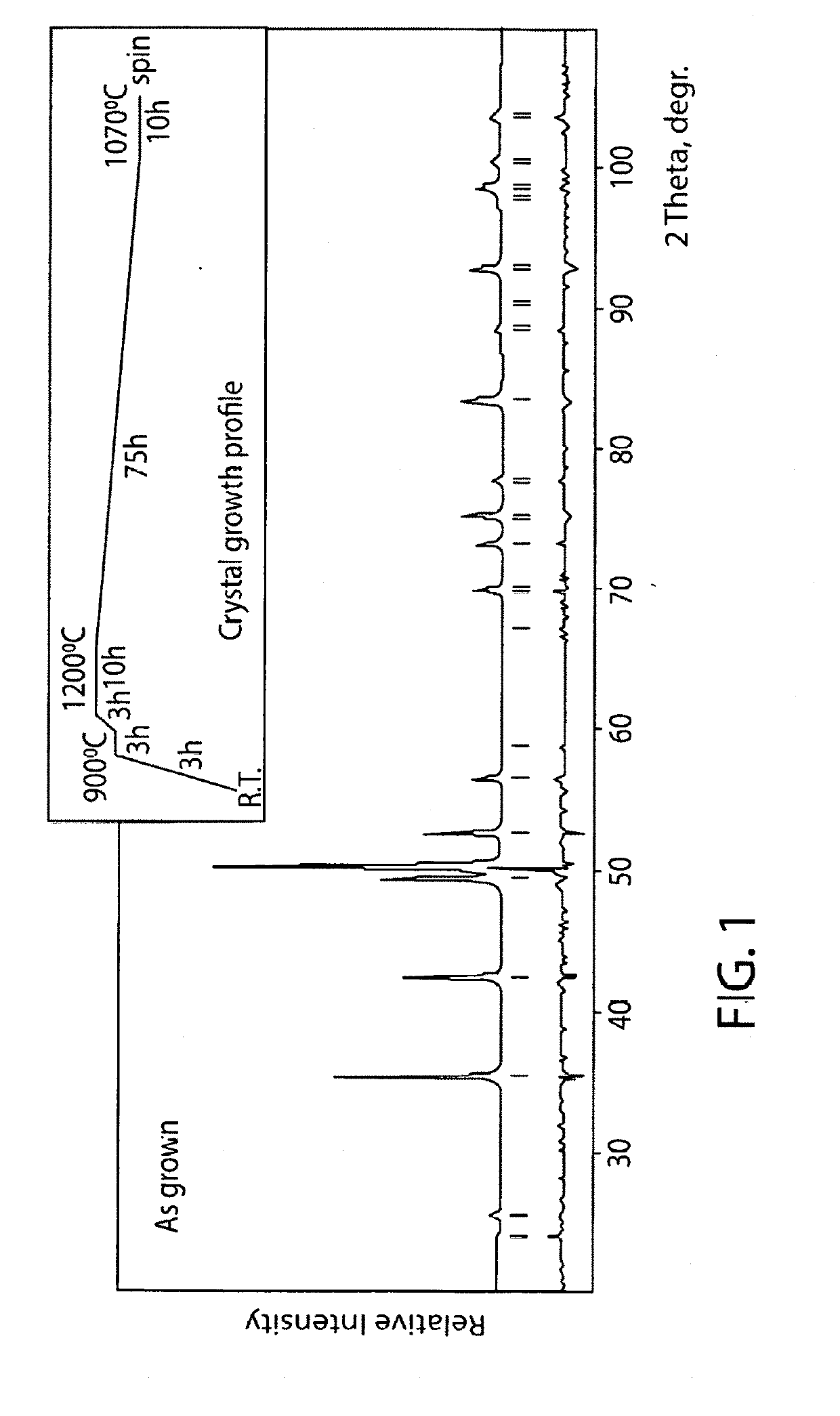
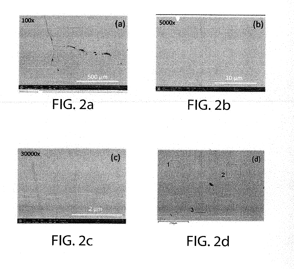
[0042]Well-formed plate-like crystals were obtained during self-flux single crystal growth from an initial loading composition Ce18Co62.32Cu19.68 in a Ta container at 1050-1070° C. The excess of flux was decanted by centrifuging at nearly reaction temperature. The exact temperature profile of this crystal growth is presented in FIG. 1 (see insert). Rietveld fitting of powder X-ray pattern taken from crushed single crystals, FIG. 1, shows that all Bragg reflections are well indexed within CaCu5-type structure (P6 / mmm. a=4.943(1), c=4.032(1) Å), providing strong argument for single-phase nature of the as-grown crystals. Additionally, SEM backscattered electron images of these crystals, FIGS. 2a-2c, revealed uniformity of...

example # 1a

Example #1A

[0050]In an attempt to reproduce the results of EXAMPLE #1 but in bulk ingot form and also for scaling-up material preparation, an approximate 8 gram are-melted button (ingot) was prepared to have the Ta-doped alloy composition of EXAMPLE #1; i.e., Ce15.5Ta0.6Co67.8Cu16.1. The alloy was prepared by arc-melting elemental constituents on a water-cooled copper hearth under partial vacuum with purified argon, rotated / flipped and re-melted twice for the homogenization.

[0051]FIG. 9a shows magnetic properties of both the bulk, non-aligned polycrystalline button (ingot) and the single crystal material after the same heat treatment; i.e., 1040° C. (10 hours)→cooling 10° C. / min.→400° C. (8 hours)→furnace cool to room temperature, i.e., cooling in the turned-off furnace to room temperature. Seemingly, both bulk and single crystal materials show nearly the same coercivity values and differ in Br and Ms, FIG. 9a. The latter result is anticipated considering polycrystalline and non-ali...

example # 2

Example #2

[0052]This example illustrates that Fe-for-Co substitutions in the Ta-doped composition of EXAMPLE #1 can result in improvement of saturation magnetization up to about 60 to about 65%.

[0053]For example, an approximate 8 gram are-melted button (ingot) was prepared to have a Fe-modified alloy composition; i.e., Ce15.5Ta0.6Co57.6Fe10.2Cu16.1 by arc-melting by arc-melting elemental constituents on a water-cooled copper hearth under partial vacuum with purified argon, rotated / flipped and re-melted twice for the homogenization.

[0054]FIG. 10 shows comparison hysteresis loops of the Fe-substituted composition bulk, unaligned sample and of the original bulk unaligned sample of EXAMPLE #1. FIG. 10 shows improvement of both coercivities and magnetizations in the Fe-substituted sample; i.e., Hc from about 6.3 to about 7.6 kOe, Br from about 2.1 to about 4.7 kG and Ms from about 3.2 to 5.2 kG.

[0055]The present invention envisions that up to about 20 atomic % of Co can be substituted by...


PUM

PropertyMeasurementUnit
temperatureaaaaaaaaaa
solution temperaturesaaaaaaaaaa

Abstract

Provided are Ce / Co / Cu permanent magnet alloys containing certain refractory metals, such as Ta and / or Hf, and optionally Fe which represent economically more favorable alternative to Sm-based magnets with respect to both material and processing costs and which retain and / or improve magnetic characteristics useful for GAP MAGNET applications.

Description

RELATED APPLICATION[0001]This application claims benefit and priority of provisional application Ser. No. 62 / 708,546 filed Dec. 12, 2017, the entire disclosure and drawings of which are incorporated herein by reference.CONTRACTUAL ORIGIN OF THE INVENTION[0002]This invention was made with government support under Grant No. DE-AC02-07CH11358 awarded by the Department of Energy. The Government has certain rights in the invention.FIELD OF THE INVENTION[0003]The present invention relates to permanent magnet alloys and to permanent magnets made from the alloys.BACKGROUND OF THE INVENTION[0004]There now exists a “GAP” (an empty niche of magnetic energy products) between present-day low-flux (ferrites, Alnico) and high-flux (Nd2Fe14B-type and SmCo5-type) magnets.[0005]For example, there is interest in so-called “GAP MAGNETS” that reach energy products of about 10-20 MGOe and that would be both advantageous with respect to the cost of constituents and their fabrication into permanent magnets...

Claims


Application Information

Patent Timeline
Patent Type & Authority Applications(United States)
IPC IPC(8): C22F1/10C22C19/07C30B29/52H01F1/047
CPCC22F1/10C22C19/07C30B29/52H01F1/047C22C2202/02H01F1/055C30B1/02
Inventor PALASYUK, ANDRIYLAMICHHANE, TEJ NATHPALASYUK, OLENAANTROPOV, VLADIMIRCANFIELD, PAUL C.MCCALLUM, RALPH W.
Owner IOWA STATE UNIV RES FOUND
Why Eureka
Try Eureka