Compositions and methods for energy storage devices having improved performance

a technology of energy storage devices and materials, applied in the direction of nickel oxides/hydroxides, cell components, electrochemical generators, etc., can solve the problems that the existing method of fabrication may impose a practical limit to various structural electrode properties, and not all such objects or advantages may be achieved

Pending Publication Date: 2019-08-01
TESLA INC
View PDF5 Cites 24 Cited by
  • Summary
  • Abstract
  • Description
  • Claims
  • Application Information

AI Technical Summary

Benefits of technology

[0005]For purposes of summarizing the disclosure and the advantages achieved over the prior art, certain objects and advantages of the disclosure are described herein. Not all such objects or advantages may be achieved in any particular embodiment. Thus, for example, those skilled in the art will recognize that the invention may be embodied or carried out in a manner that achieves or optimizes one advantage or group of advantages as taught herein without necessarily achieving other objects or advantages as may be taught or suggested herein.

Problems solved by technology

Furthermore, existing methods of fabrication may impose a practical limit to various structural electrode properties.
Not all such objects or advantages may be achieved in any particular embodiment.

Method used


Image

  • Compositions and methods for energy storage devices having improved performance
  • Compositions and methods for energy storage devices having improved performance
  • Compositions and methods for energy storage devices having improved performance

Examples


example 1

ctrodes

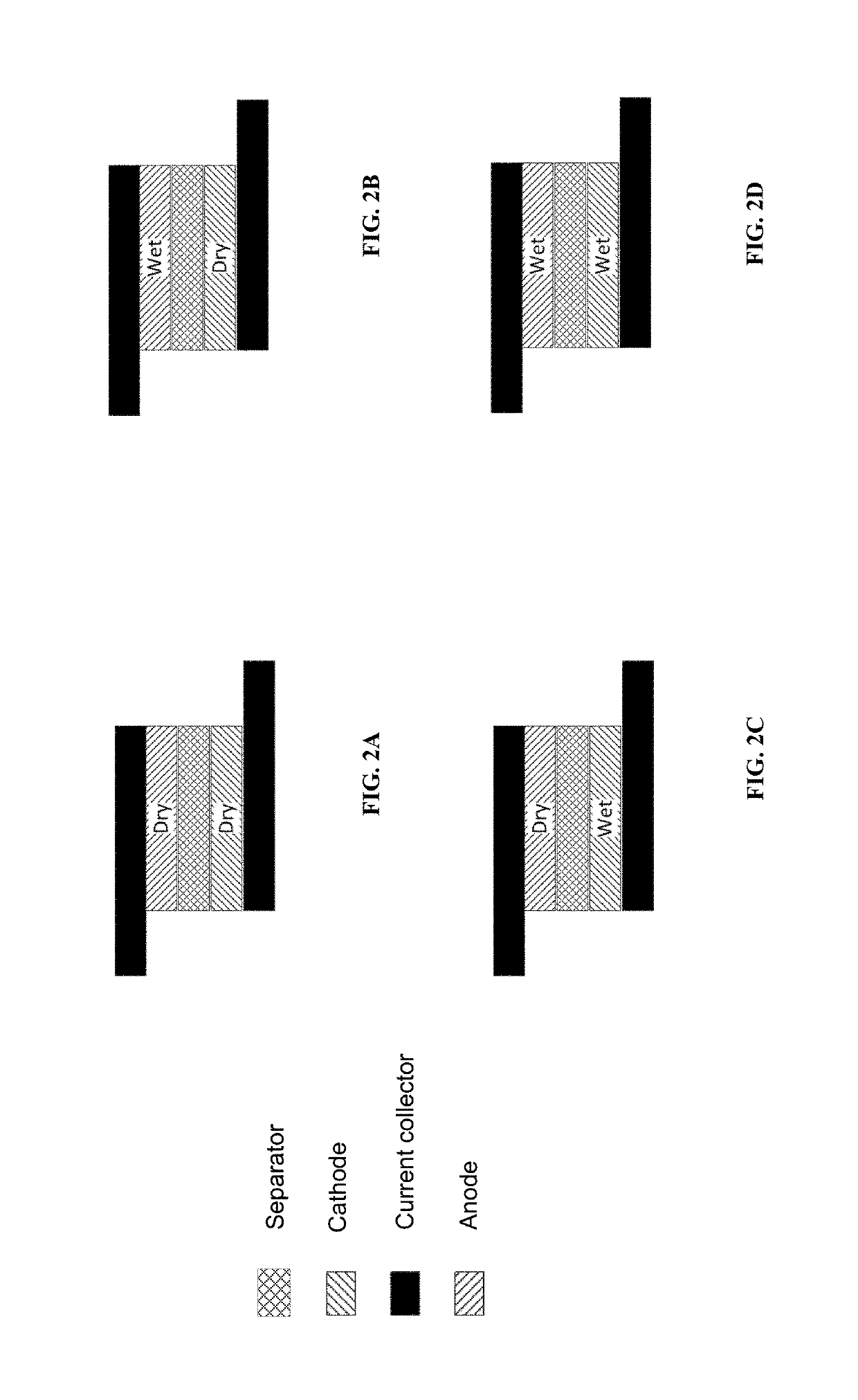
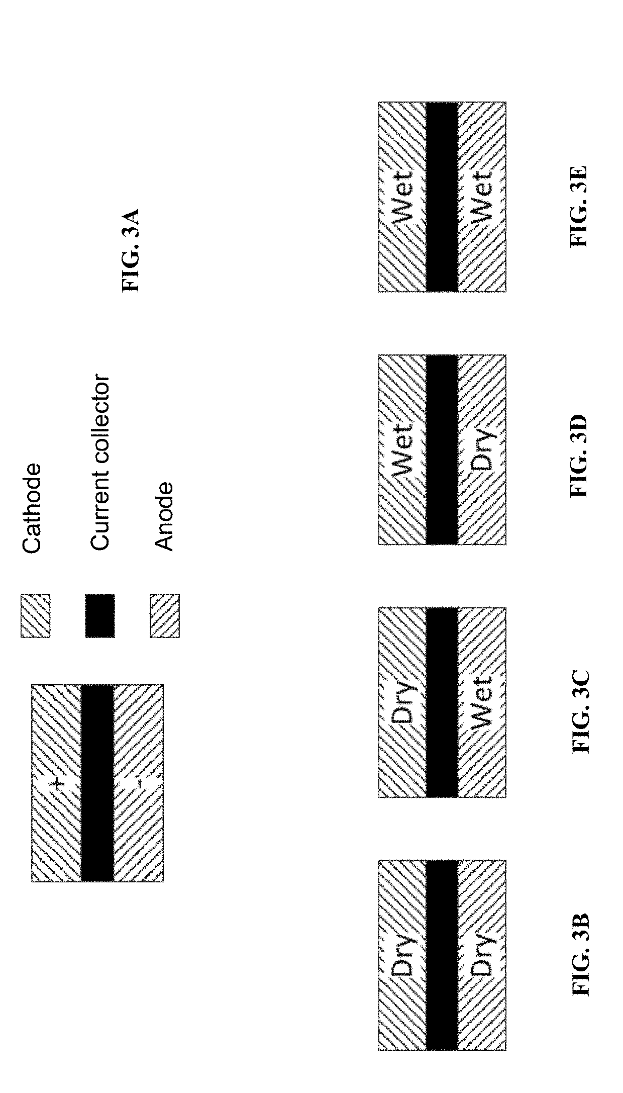
[0100]Dry battery anodes were fabricated, which included 96% by weight graphite and 4% by weight binder, wherein the binder included 2% PTFE, 1% CMC and 1% PVDF by weight totaling the 4% of binder by weight. Cathodes were also fabricated in a dry process, the cathodes including 94% by weight NMC622, 3% by weight conductive additive, and 3% by weight polymer binder. In addition, wet process electrodes were fabricated having the following compositions: the wet process anode included 95.7% by weight graphite, 1% conductive additive, and 3.3% by weight polymer binders, and the wet process cathode included 91.5% by weight active component and 4.4% by weight conductive additive and 4.1% by weight polymer binder. Other electrode film compositions can be envisioned and prepared, and the disclosure herein is not limited to the specific compositions disclosed.

[0101]Four lithium ion batteries were assembled, following the scheme of Table 1. Each lithium ion battery of Table 1 was tested...

example 2

Electrode Specific Capacity

[0110]Table 3 provides the electrode specifications for thick NMC622 cathode and thick graphite anode. The NMC622 cathode is composed of 94 wt % NMC622, 2 wt % porous carbon, 1 wt % conductive carbon and 3 wt % PTFE. The graphite anode is composed of 96 wt % graphite, 1.5 wt % CMC, 0.5 wt % PVDF and 2 wt % PTFE. The half-cell 1st cycle results are captured in FIGS. 12 and 13 for dry NMC622 and graphite electrode, respectively. The half-cell in FIG. 12 was charged at room temperature at a constant current of C / 20 to a 4.3V cutoff, then a constant voltage to a C / 40 cutoff, and then discharged at room temperature at a constant current of C / 20 to a 2.7V cutoff. The half-cell in FIG. 13 was charged at room temperature at a constant current of C / 20 to a 5 mV cutoff, then a constant voltage to a C / 40 cutoff, and the discharged at room temperature at a constant current of C / 20 to a 2V cutoff. The first cycle specific discharge capacity for both polarities exceeds ...

example 3

ctrode Charge and Discharge Performance

[0112]FIGS. 15A and 15B provide the discharge rate voltage profiles for dry and wet coated electrodes, respectively. The active material used in both coating technologies are NMC622 for the cathode and graphite for the anode. The wet NMC622 cathode is composed of about 92 wt % NMC622, 4 wt % conductive carbon and 4 wt % PVDF. The wet NMC622 cathode was formed with a 41.0 mg / cm2 loading, which gave a 155 μm thick film, a 36% porosity, and a 2.66 g / cm3 electrode film density. The wet graphite anode is composed of about 96 wt % graphite, 1 wt % conductive carbon and 3 wt % CMC / styrene-butadiene binder. The wet graphite anode was formed with a 24.5 mg / cm2 loading, which gave a 182 μm thick film, a 37.5% porosity, and a 1.35 g / cm3 electrode film density.

[0113]The dry NMC622 cathode is composed of about 95 wt % NMC622, 2 wt % porous carbon, 1 wt % conductive carbon and 2 wt % PTFE. The dry graphite anode is composed of about 96 wt % graphite, 1 wt % ...


PUM

PropertyMeasurementUnit
thicknessaaaaaaaaaa
porosityaaaaaaaaaa
densityaaaaaaaaaa

Abstract

Provided herein are energy storage devices comprising at least one dry process, self-supporting electrode film having improved performance. The improved performance may be realized as improved electrode material loading, improved active material loading, improved active material density, improved areal capacity, improved specific capacity, improved areal energy density, improved energy density, improved specific energy density, or improved Coulombic efficiency.

Description

INCORPORATION BY REFERENCE TO ANY PRIORITY APPLICATIONS[0001]Any and all applications for which a foreign or domestic priority claim is identified in the Application Data Sheet as filed with the present application are hereby incorporated by reference under 37 CFR 1.57. This application claims the benefit of priority under 35 U.S.C. § 119(e) of U.S. Provisional Application No. 62 / 590,110, filed Nov. 22, 2017.BACKGROUNDField[0002]The present invention relates generally to energy storage devices, and specifically to materials and methods for dry electrode energy storage devices having improved performance.Description of the Related Art[0003]Electrical energy storage cells are widely used to provide power to electronic, electromechanical, electrochemical, and other useful devices. Such cells include batteries such as primary chemical cells and secondary (rechargeable) cells, fuel cells, and various species of capacitors, including ultracapacitors. Increasing the operating power and ene...

Claims


Application Information

Patent Timeline
Patent Type & Authority Applications(United States)
IPC IPC(8): H01M4/131H01M4/133H01M4/62H01M4/04H01M10/0525
CPCH01M4/131H01M4/133H01M4/623H01M4/0404H01M10/0525H01M2004/021H01M2004/028H01M2004/027C01G53/04C08L1/00H01M4/525H01M4/587H01M4/622Y02E60/10H01M4/13H01M4/139H01M4/505H01M4/0471H01M4/0435
Inventor SHIN, JOON HODUONG, HIEU MINHFEIGENBAUM, HAIM
Owner TESLA INC
Why Eureka
Try Eureka