
Thermal desorption tube collection system and method

a collection system and desorption tube technology, applied in the operation mode of machines, instruments, lighting and heating apparatuses, etc., can solve the problems of low method detection limits (mdls), and achieve the effect of simple and effective approach, increased material collection, and low method detection limits

Active Publication Date: 2019-08-29
MLS ACQ INC
View PDF0 Cites 8 Cited by
  • Summary
  • Abstract
  • Description
  • Claims
  • Application Information

AI Technical Summary

Benefits of technology

The invention relates to a system for collecting and detecting gases, particularly using a cooled TDT (a device that is heated and cooled to collect and desorb samples) that can be operated standalone, without needing a power source. The system can be portable and can collect larger samples than uncooled TDTs. It can also have two channels for switching between collection and desorption. The technical effects of the invention include improving the efficiency of gas collection and detection, making it possible to collect larger samples, and providing a portable and independent system for gas detection.

Problems solved by technology

Samples can be concentrated, resulting in lower method detection limits (MDLs).

Method used


Image

  • Thermal desorption tube collection system and method
  • Thermal desorption tube collection system and method
  • Thermal desorption tube collection system and method

Examples


example 1

ling of Acrolein, Acetaldehyde and Formaldehyde on A2 TDTs

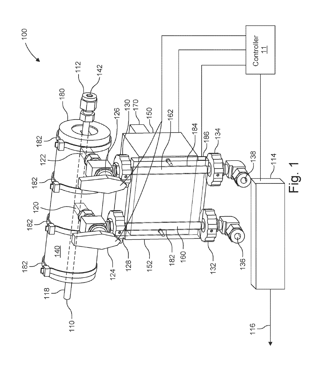
[0128]The purpose of this experiment was to determine a sampling temperature that yields >50% recovery for acrolein, acetaldehyde and formaldehyde on A2 TDTs (Gerstel). A 191° C. sample stream consisting of 2% moisture, acrolein, acetaldehyde and formaldehyde in nitrogen was run to the sampling manifold. A 2 L sample was collected on a pair of A2 TDTs loaded into the TDT collection system 100 at a rate of 100 mL / min for 20 min, with one TDT at room temperature and one in a 0° C. container. Sampling was repeated twice more for a total of three consecutive sample pairs (Sample 6, 7 and 8). After sampling was complete, TDTs were immediately transferred to the refrigerator, where they were stored for 10-30 minutes. TDTs were run on GC and analyzed using absorbance spectra and manual validation. Results for Sample 7 are not shown below because the run data for the 0° C. TDT was not useable. The

A2 TDTsSample 6Sample 8Average23° C.0...

example 2

alysis

[0130]Since, in many instances, the biogas analysis will not require a detailed breakdown to the level of each and every oil species present, a reading for an entire class is sufficient. Thus, in some implementations, the system and method described above can be used to measure oil as a single component at trace amounts of 10 to 20 ng, for example.

[0131]The IR spectra can be analyzed by a suitable technique. Some embodiments rely on calibrations based on decane, undecane, dodecane spectra to determine the mass level of oil present (in ng). Dodecane, for example, is commonly used to match heavy hydrocarbons like diesel fuel and oil. Techniques described in U.S. patent application Ser. No. 16 / 113,856, filed on Aug. 27, 2018, with the title Carbon Ladder Calibration, incorporated herein by this reference in its entirety, can be used to predict which compound is most similar to the sample and use this compound to obtain the most precise reading of oil mass. It is expected that the...


PUM

PropertyMeasurementUnit
freezing pointaaaaaaaaaa
temperatureaaaaaaaaaa

Abstract

A thermal desorption tube collection system uses a thermoelectric cooler to collect and concentrate gas samples. In some modes, the operation of the cooler is reversed to flow the concentrated sample directly into a separator such as a gas chromatography system. Components resolved in time by a thermal desorption separator accumulate in a sample cell and are analyzed by electromagnetic radiation-based spectroscopic techniques. Also presented are methods for analyzing biogas samples.

Description

RELATED APPLICATIONS[0001]This application claims the benefit under 35 USC 119(e) of U.S. Provisional Application No. 62 / 636,628, filed on Feb. 28, 2018 and U.S. Provisional Application No. 62 / 636,623, filed on Feb. 28, 2018. All of the afore-mentioned applications are incorporated herein by this reference in their entirety.BACKGROUND OF THE INVENTION[0002]Gas Chromatography (GC) is used to resolve a mixture into its various components according to retention profiles of the different molecules passing through the GC column.[0003]While the technique can separate mixtures containing hundreds of substances, identifying the molecules that elute from the column is more problematic. To address the need for rapid and sensitive identification of the molecular species present, GC has been integrated with techniques such as mass spectrometry (MS) or Fourier transform infrared (FTIR) spectrometry.[0004]Gas chromatography-mass spectrometry (GC-MS) is probably the most widespread tandem techniqu...

Claims


Application Information

Patent Timeline
Patent Type & Authority Applications(United States)
IPC IPC(8): G01N30/12G01N30/74G01N30/72G01N30/60
CPCG01N2030/743G01N30/12G01N30/74G01N30/7206G01N2030/008G01N2030/128G01N2030/025G01N30/6073F25B21/02G01N1/2214G01N1/4022G01N30/08G01N2001/2282G01N2001/4033G01N2030/121G01N2030/123
Inventor SPARTZ, MARTIN L.KLEMPNER, ADAM R.MCPARTLAND, KELLY RENEE
Owner MLS ACQ INC
Learn More