Chemical Wall-Treatment Method That Reduces the Formation of Coke

a wall treatment and chemical technology, applied in the direction of solid-state diffusion coating, metallic material coating process, coating, etc., can solve the problems of coking phenomena, deterioration of the conductivity of the walls, and loss of head

Inactive Publication Date: 2019-12-26
TOTAL RAFFINAGE CHIM +3
View PDF0 Cites 0 Cited by
  • Summary
  • Abstract
  • Description
  • Claims
  • Application Information

AI Technical Summary

Benefits of technology

[0011]To this end, there is provided a process for the treatment of a wall made of Fe—Ni—Cr metal alloy of an industrial reactor which reduces the formation of coke on the said surface when it is subjected to operational conditions favourable to coking, the metal alloy comprising in particular, within its structure, carbides, some of which can show on the surface. For example, the metal alloy contains at least 5% by weight of iron, at least 18% by weight of chromium, at least 25% by weight of nickel and at least 0.05% by weight of carbon.
[0015]Without wishing to be committed to a theory, the removal from the surface of at least a part of the carbides by electrolytic dissolution makes it possible to reduce the formation of coke.
[0016]Such a surface treatment stage exhibits the advantage of being easy to carry out and relatively inexpensive.
[0019]Advantageously, after the chemical treatment stage, a stage of oxidation of the wall can be envisaged, which makes it possible to further reduce the formation of coke. Without wishing to be committed to a theory, the surface treatment appears to promote the formation of a homogeneous oxidized layer and to thus reduce the formation of coke.
[0064]Usually, the objective of this type of impact surface treatment is to compress the substance under the impacted surface: this compressed substance tends to regain its initial volume, resulting in high residual compressive stresses. This makes it possible to significantly increase the lifetime of a part made of alloy as virtually all of the fatigue and corrosion failures under tension are initiated at the surface of such parts.
[0066]While the chemical treatment stage brings about the formation of cavities, the permanent plastic deformation obtained by the implementation of the mechanical treatment stage makes it possible to fill these cavities in again, at least partially. In addition, covering of the carbides initially present at the surface—in other words covering of the carbides showing on the surface and / or located in the immediate vicinity of the surface before the mechanical treatment—which have not been dissolved by the chemical treatment stage is also observed. Surprisingly, this modification of the surface, which limits the access to the carbides trapped inside the metal alloy, also makes it possible to reduce the formation of coke.

Problems solved by technology

The walls of the reactors of some units of the petrochemical or chemical industry are sometimes subjected to very severe operating conditions which can result in phenomena of coking.
This deposition of coke can result in a fouling of the tubes, causing a head loss, a deterioration in the conductivity of the walls and a decrease in the yields.
It is then necessary to shut down the unit in order to remove the coke formed, an operation which is harmful to the productivity of the unit.

Method used


Image

  • Chemical Wall-Treatment Method That Reduces the Formation of Coke
  • Chemical Wall-Treatment Method That Reduces the Formation of Coke
  • Chemical Wall-Treatment Method That Reduces the Formation of Coke

Examples


example 1

emical Treatment of the Surface

[0099]In this example, the sample is subjected to an electrolytic dissolution chemical treatment.

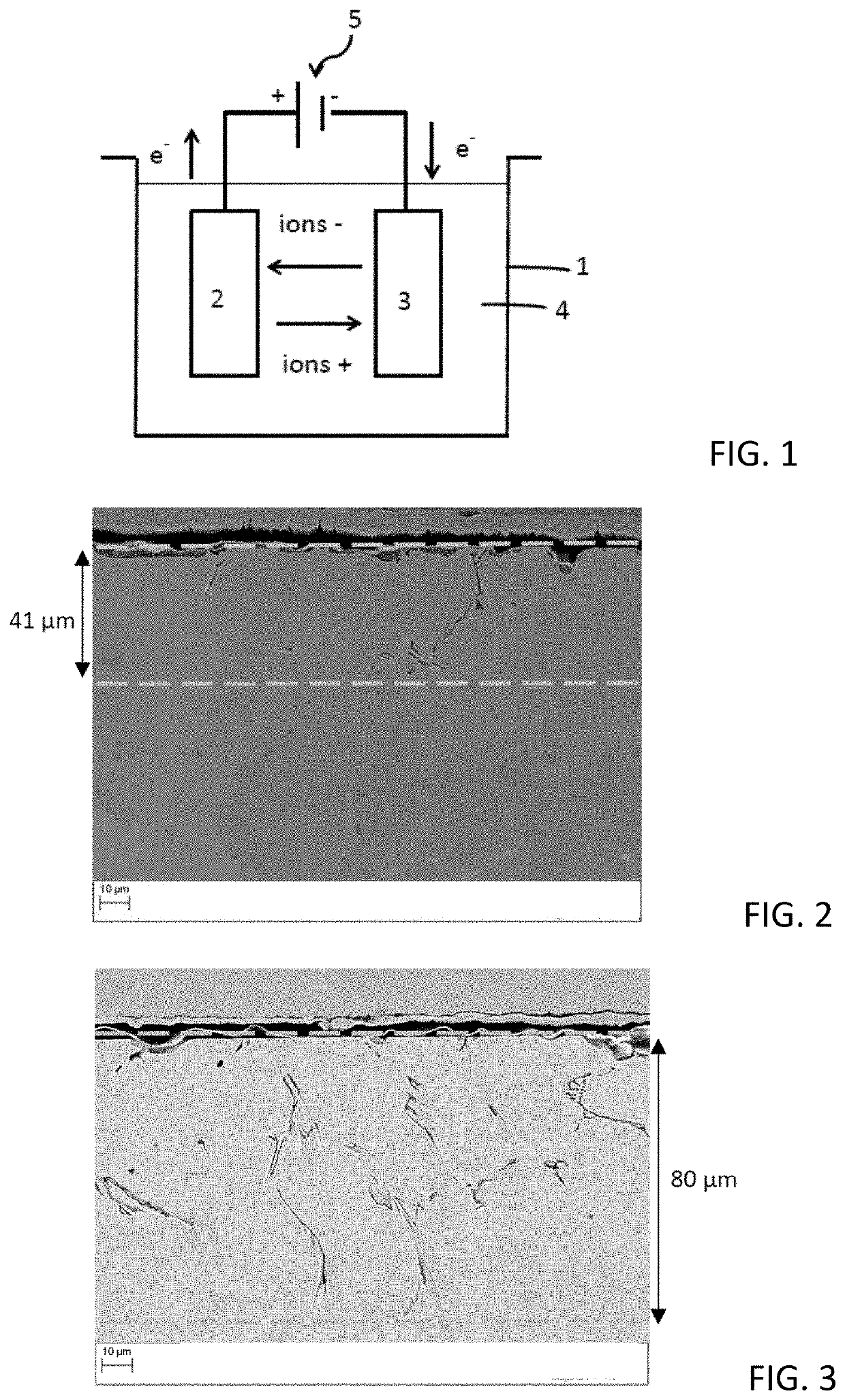
[0100]The sample to be tested is placed at the anode of an electrolysis cell, such as described in FIG. 1, the cathode being a metal plate made of stainless steel or of graphite, with dimensions similar to or greater than those of the sample. The anode and cathode are separated by a distance of approximately 1 cm, the plates being substantially parallel inside the electrolysis cell.

[0101]An electrolytic solution is prepared by dissolving, with mechanical stirring, 135 g of NaOH (in the form of pellets) in 1 l of distilled water and then the electrolysis cell is filled with the solution obtained. The chloride content of the solution is less than 10 ppm by weight.

[0102]A potential difference is applied between the anode (sample) and the cathode.

[0103]Two series of five and four tests were carried out on HP 25-35 alloys, which were all polished before being pl...

example 2

l Surface Treatment / Shot Peening

[0111]A polished HP 25-35 alloy sample is subjected to shot peening in a sleeve sandblasting chamber. The parameters used are as follows:[0112]Particles: glass beads Ø 100-200 μm[0113]Projection distance: approximately 15 cm[0114]Duration of the projection: 15 seconds for a sample of a few cm2 [0115]Carrier gas: compressed air under a controlled pressure of 2.5 to 3.5 bars, nozzle diameter 6 to 8 mm, 40 litres of particles in a closed circuit.

[0116]A sample M1 is obtained.

example 3

l Surface Treatment / Sandblasting (Alumina Blasting)

[0117]A polished HP 25-35 alloy sample is subjected to alumina blasting in a sleeve sandblasting chamber. The parameters used are as follows:[0118]Particles: brown corundum (Al2O3) Ø 250-400 μm[0119]Projection distance: approximately 15 cm[0120]Duration of the projection: 15 seconds for a sample of a few cm2 [0121]Carrier gas: compressed air under a controlled pressure of 2.5 to 3.5 bars, nozzle diameter 6 to 8 mm, 40 litres of abrasive particles in a closed circuit.

[0122]A sample M3 is obtained.


PUM

PropertyMeasurementUnit
depthaaaaaaaaaa
diameteraaaaaaaaaa
pressureaaaaaaaaaa

Abstract

The invention relates to a process for the treatment of a wall made of Fe—Ni—Cr metal alloy of an industrial reactor which reduces the formation of coke on the said wall when it is subjected to operational conditions favourable to coking, the metal alloy comprising, within its structure, carbides, some of which show on the surface. The process comprises a chemical surface treatment stage, during which at least a part of the carbides initially present in the alloy is dissolved by electrolytic decomposition, under conditions suitable for dissolving at least a part of these carbides, in particular chromium carbides.

Description

TECHNICAL FIELD[0001]The invention relates to a process for the surface treatment of a metal wall which has the effect of reducing the formation of coke at the surface of this wall. More specifically, the invention relates to a process for the surface removal of carbides from a wall made of metal alloy, in particular by chemical treatment. The invention also relates to the use of a metal wall treated by the treatment process in a process for the treatment of hydrocarbons.STATE OF THE ART[0002]The walls of the reactors of some units of the petrochemical or chemical industry are sometimes subjected to very severe operating conditions which can result in phenomena of coking. For example, the manufacture of alkenes, monomers valued in the polymer industry, is obtained by cracking oil-derived hydrocarbons at temperatures of the order of 800 to 900° C. In this type of process, a mixture of hydrocarbons and steam is circulated at high speed in reactors, generally formed of metal tubes, oft...

Claims


Application Information

Patent Timeline
Patent Type & Authority Applications(United States)
IPC IPC(8): C25F3/06C23C8/02B24C1/04
CPCC25F3/06C23C8/02B24C1/04
Inventor AUGUSTIN, CHRISTELCAZOTTES, SOPHIEVACHÉ, NICOLASSTEYER, PHILIPPEDURET THUAL, CLAUDEDUPOIRON, FRANÇOIS
Owner TOTAL RAFFINAGE CHIM
Why Eureka
Try Eureka