Microtube Sensor For Physiological Monitoring

a physiological monitoring and microtube technology, applied in the direction of angiography, force measurement by measuring optical property variation, instruments, etc., can solve the problems of increasing the wearability of the sensor for the user, reducing the electronics components, and not being able to achieve the planar substrate effect, etc., to achieve the effect of improving compliance and comfort, reducing electronics components, and high sensitivity

Active Publication Date: 2020-01-23
NAT UNIV OF SINGAPORE
View PDF0 Cites 7 Cited by
  • Summary
  • Abstract
  • Description
  • Claims
  • Application Information

AI Technical Summary

Benefits of technology

[0004]Embodiments of the invention have distinctive characteristics that provided benefits and advantages over existing technologies. The microtube sensor possesses a footprint (e.g., outer diameter) of less than about 120 μm. Its tiny footprint is approximately a cross-section of a strand of hair, which is one of the smallest in the existing technologies. This enables users to apply the sensor almost indistinguishably, thereby improving compliance and comfort. Furthermore, the tubular structure allows conformability over 3D curvatures, which cannot be achieved with planar substrates.
[0005]In addition, due to the manufacturing techniques used for making the mic...

Problems solved by technology

Furthermore, the tubular structure allows conformability over 3D curvatures, which cannot be achieved with planar substrates.
This can further reduce the electronics component...

Method used


Image

  • Microtube Sensor For Physiological Monitoring
  • Microtube Sensor For Physiological Monitoring
  • Microtube Sensor For Physiological Monitoring

Examples


example 1

ement Analysis

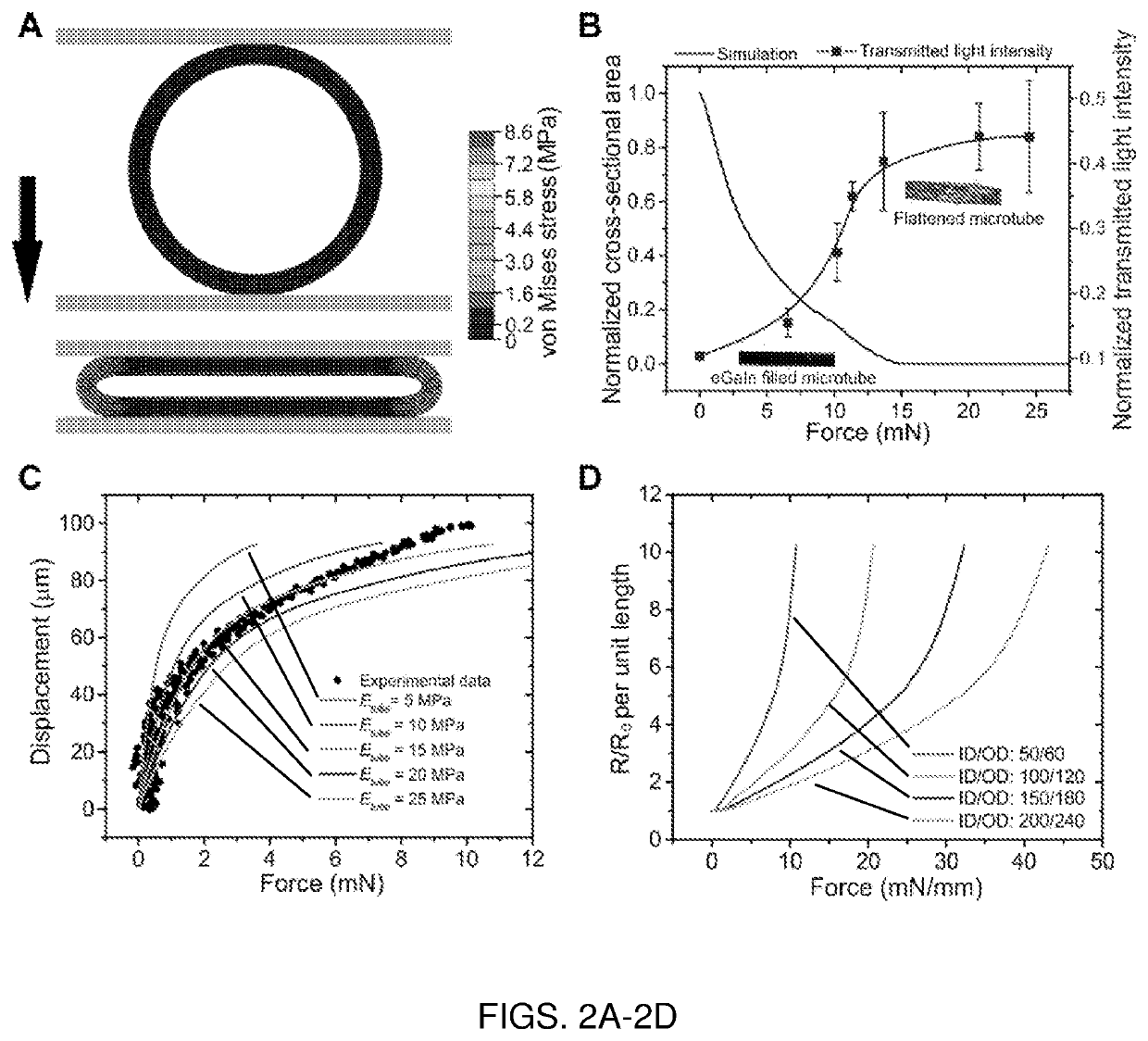
[0088]Finite element modeling of the microtube tactile sensors was performed using ABAQUS CAE for both 2D plane strain and 3D analyses, depending on the geometry of the top pitch (i.e., the crosshead compressing the microtube). Due to symmetry, half and quarter models were established for 2D plane strain and 3D analyses, respectively. General static analysis mode was selected with hard and frictionless contact established between the top pitch and the top half outer surface of the microtube, bottom plate and lower half outer surface of the microtube, as well as the microtube inner surface. Hybrid and linear elements with reduced integration were used for contact analysis. The tube wall was divided into 6 layers in the large stress regions near the mid-plane, and 4 layers in the other regions. Flexible polydimethylsiloxane (PDMS) was assumed to be elastic,[10] and Poisson's ratio was chosen to be 0.49.

example 2

sign and Fabrication

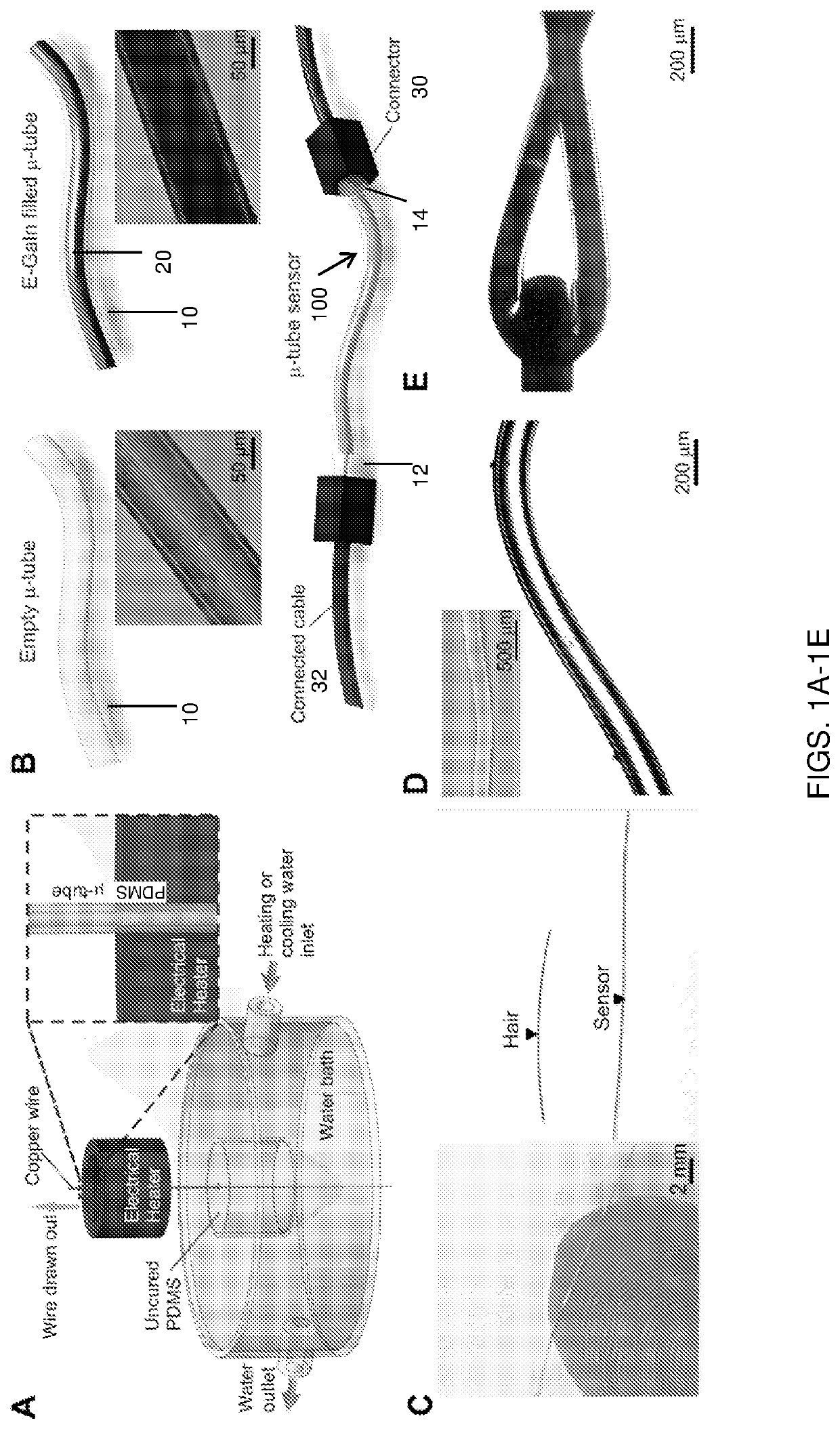
[0089]To create the microtube, a metal filament (e.g., wire) was first immersed vertically into a freshly mixed PDMS base and curing agent, 10:1 (w / w) (e.g., mixture of Sylgard 184 silicone elastomer base and Sylgard 184 silicone elastomer curing agent, 10:1 by weight). The metal filament was drawn out of the PDMS pool using a rotary motor at a velocity of 2 to 4 mm / s. Simultaneously, hot water of ˜100° C. was added to the surrounding PDMS pool to initiate PDMS curing. When the metal wire was drawn out vertically above the liquid level, it was further cured by hot air at ˜95° C. in a cylindrical heating unit. To maintain the optimal viscosity of the PDMS for even coating around the metal filament, cold water would be added into the PDMS pool surroundings to prolong curing time. Next, the metal wire was peeled off during a sonication process in acetone solution which would wash off unreacted elastomer curing agent and caused slight swelling in the polymer—loosenin...

example 3

Sensing, Durability and Mechanical Forces Differentiation

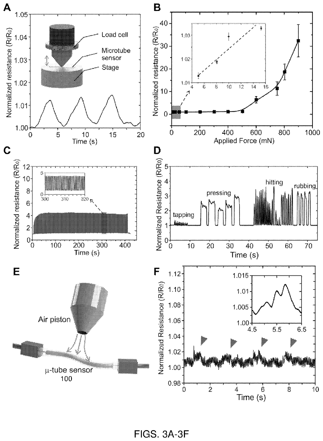
[0090]The liquid-based microtube tactile sensor was subjected to compressive ramp-hold-release loads starting from 10 mN to 100 mN using a universal load machine (5848 MicroTester, Instron, Norwood, Mass.), as schematically illustrated in FIG. 3A. The ramp and release rates were set at 5 mm / min. The electrical response of the tactile sensor upon different load applications was continuously monitored and recorded using a customized data logging microprocessor at 20 Hz.


PUM


Abstract

A soft, flexible microtube sensor and associated method of sensing force are described. A liquid metallic alloy is sealed within a microtube as thin as a strand of human hair to form the physical force sensing mechanism. The sensor is hardly distinguishable with the naked eye, and can be used for the continuous biomonitoring of physiological signals, such as unobtrusive pulse monitoring. Also described is a method of fabricating the microtube sensor and wearable devices incorporating one or more microtube sensors.

Description

RELATED APPLICATION(S)[0001]This application claims the benefit of U.S. Provisional Application No. 62 / 465,002, filed on Feb. 28, 2017. The entire teachings of the above application are incorporated herein by reference.BACKGROUND[0002]Recent years have seen significant attention devoted to flexible electronics, leading to tremendous progress in soft and wearable sensors. Compared to rigid sensors, sensors that are flexible, stretchable, and bendable have shown enormous potential in health monitoring, soft robotics, electronics skins, and prosthetics. Elastic mechanical properties are the key factors for wearability and imperceptibility to enable conformal skin contact for in situ monitoring. However, conventional silicon-based devices and many conductive materials are mechanically stiff and brittle. To overcome this, some approaches have deposited conductive layers of carbon nanotubes, nanoparticles, nanowires, and two-dimensional materials, onto stretchable substrates, resulting in...

Claims


Application Information

Patent Timeline
IPC IPC(8): G01N27/06A61B5/021G01L1/24A61B5/024
CPCG01N27/06A61B2562/028A61B5/02108A61B2562/0261A61B5/02444G01L1/245A61B5/02007A61B5/1038A61B5/6807G01L1/20
Inventor YEO, JOO CHUANXI, WANGYU, LONGTENGLIM, CHWEE TECK
Owner NAT UNIV OF SINGAPORE
Why Eureka
Try Eureka