
Integrated package structure for MEMS element and asic chip and method for manufacturing the same

a technology of integrated circuits and components, applied in the field of microelectromechanical systems (mems) technology, can solve the problems of affecting cmos circuits, material waste and increased costs, complicated vacuum package technical solutions based on tsv technology, etc., to improve the defect-free rate of mems elements, reduce the overall volume of mems elements, and reduce bonding temperature

Active Publication Date: 2020-08-20
SONICMEMS (ZHENGZHOU) TECH CO LTD +1
View PDF0 Cites 1 Cited by
  • Summary
  • Abstract
  • Description
  • Claims
  • Application Information

AI Technical Summary

Benefits of technology

The patent text describes a new method and structure for integrating a MEMS element and an ASIC chip. The technique uses an organic compound called BCB, which has lower bonding temperature and better stability compared to other bonding methods. This results in a more reliable and efficient bonding process that can be compatible with existing integrated circuit manufacturing processes. Additionally, the new method allows for the formation of a closed cavity structure and reduces the overall volume of the MEMS element, making it more portable and easier to test and apply. Overall, the technical solution described in the patent text provides a convenient way to integrate MEMS elements into integrated circuit packages.

Problems solved by technology

However, the wafer scale vacuum package technical solution based on the TSV technology is complicated and has a great influence for IC designs.
As the scale down speed for IC technology is much faster than the scale down speed for MEMS technology, requiring the area of the ASIC to be in consistent with the MEMS chip results material waste and increased costs.
On the other hand, although the Post-CMOS monolithic integration technical solution has fewer requirements for CMOS manufacturing processes, CMOS circuits are affected greatly when the AlN MEMS element undergoes high-temperature processing procedures.
The flip chip technology cannot make the AlN MEMS element to form a closed cavity structure.

Method used


Image

  • Integrated package structure for MEMS element and asic chip and method for manufacturing the same
  • Integrated package structure for MEMS element and asic chip and method for manufacturing the same
  • Integrated package structure for MEMS element and asic chip and method for manufacturing the same

Examples


Embodiment Construction

[0028]The instant disclosure will be further described in detail below with reference to the accompanying drawings and embodiments. The drawings of the present invention are merely illustrative for easier understanding of the instant disclosure, and the specific proportions thereof can be adjusted according to design requirements. The above-described relative relationship of the elements in the drawings described herein will be understood by those skilled in the art to refer to the relative positions of the members, and therefore, the same members may be turned over and the like, which are all within the scope of the instant disclosure.

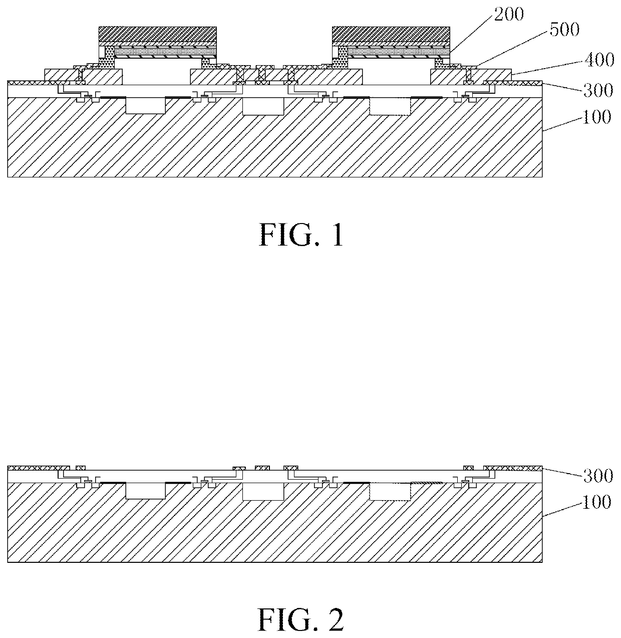
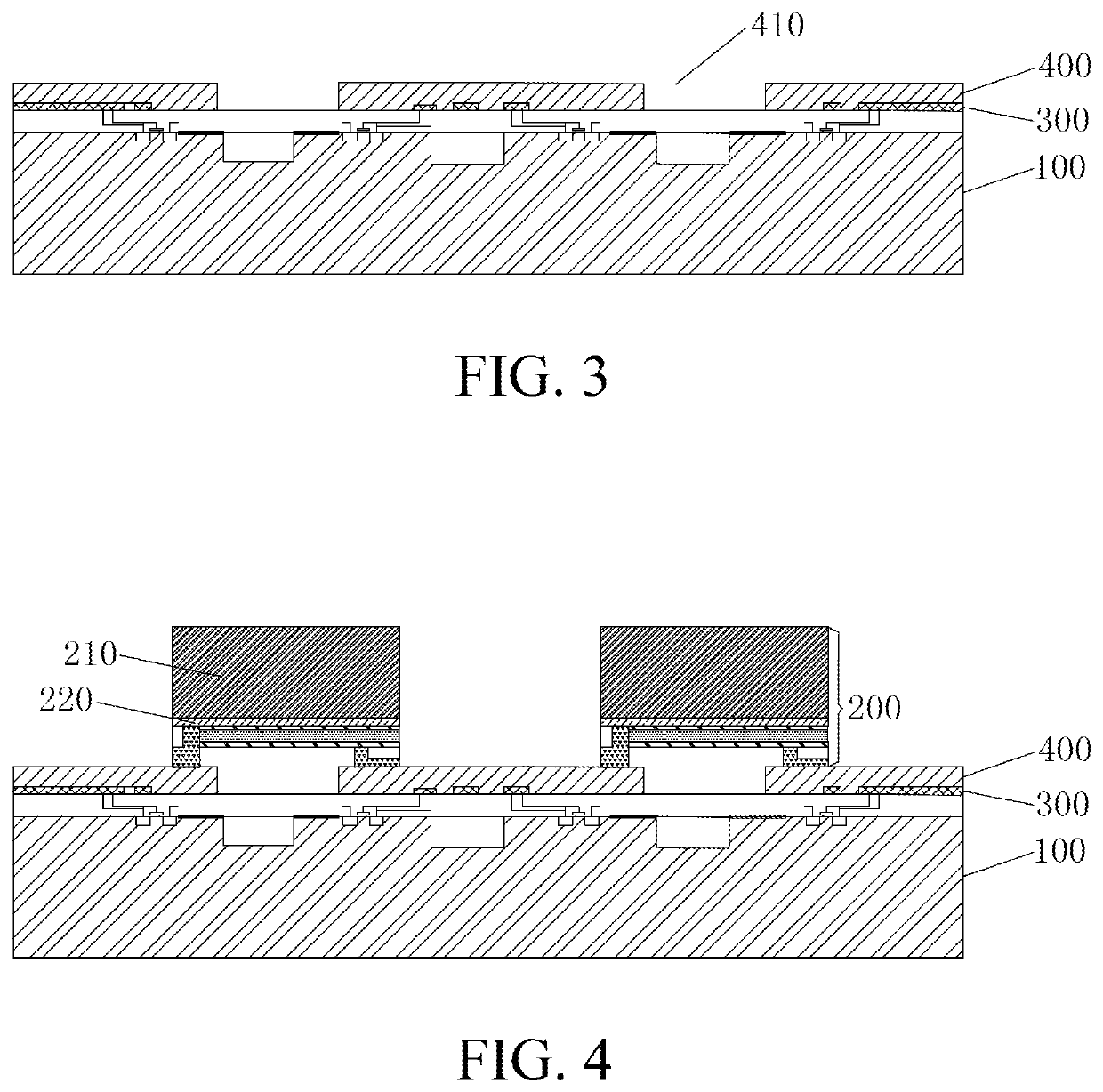
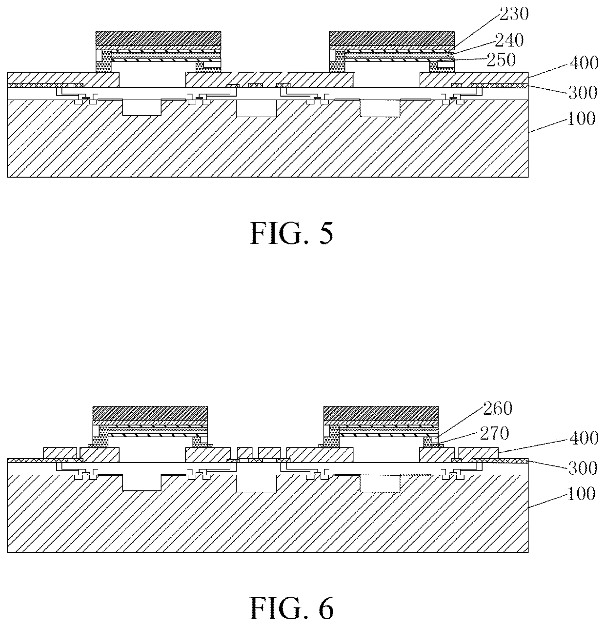
[0029]As shown in FIG. 1, an integrated package structure for MEMS element and ASIC chip according to an exemplary embodiment of the instant disclosure is illustrated. The integrated package structure comprises an ASIC wafer 100, an MEMS element 200, a re-layout layer 300, a bonding layer 400, and a metal connection member 500. The re-layout layer 300...


PUM

PropertyMeasurementUnit
thicknessaaaaaaaaaa
thicknessaaaaaaaaaa
thicknessaaaaaaaaaa

Abstract

An integrated package method for MEMS element and ASIC chip includes forming a re-layout layer on a front surface of an ASIC wafer; coating an organic compound layer on the re-layout layer and applying a lithography process to the organic compound layer to from a microcavity array; aligning and bonding an electrode connection pad layer on a front surface of an MEMS element with the microcavity array to form a closed cavity structure; thinning and exposing a silicon substrate on a back surface of the MEMS element to a desired thickness; applying the lithographic process on the MEMS element to expose the electrode connection pad layer and an electrical contact area of the re-layout layer; and manufacturing a metal connection member connected to the electrode connection pad layer and the electrical contact area. An integrated package structure for MEMS element and ASIC chip is also provided.

Description

CROSS-REFERENCE TO RELATED APPLICATION[0001]This non-provisional application claims priority under 35 U.S.C. § 119(a) to Patent Application No. 201910124346.5 filed in China, P.R.C. on Feb. 19, 2019, the entire contents of which are hereby incorporated by reference.BACKGROUNDTechnical Field[0002]The instant disclosure relates to microelectromechanical systems (MEMS) technology, in particular, to an integrated package structure for MEMS element and application-specific integrated circuit (ASIC) chip and method for manufacturing the same.Related Art[0003]The aluminum nitride (AlN) MEMS element is a sensor or an actuator using AlN as the piezoelectric materials. The AlN MEMS elements are developed in a trend of minimization and small-scale integration, in which not only the size reduction and the performance improvement are pursued but the cost reduction is also concerned. The AlN materials provide proper heat conduction property, higher dielectric constant, and are compatible with the...

Claims


Application Information

Patent Timeline
Patent Type & Authority Applications(United States)
IPC IPC(8): B81C1/00B81B7/00
CPCB81C2201/0159B81C2203/032B81B2207/012B81C1/00238B81B2201/0271B81B2207/07B81C2201/0125B81C2203/0792B81B7/0006B81C2203/054
Inventor MA, SHENG-LINGONG, DANCHIU, YI-HSIANG
Owner SONICMEMS (ZHENGZHOU) TECH CO LTD
Learn More