Network Service and Transformer Safety Protector

a transformer safety protector and network service technology, applied in the direction of transformer/inductance details, contact, emergency protective circuit arrangement, etc., to achieve the effect of easy troubleshooting or conduct, high reliability, and less maintenan

Active Publication Date: 2020-10-08
CARTE INT +1
View PDF0 Cites 7 Cited by
  • Summary
  • Abstract
  • Description
  • Claims
  • Application Information

AI Technical Summary

Benefits of technology

[0101]It is also an object of the present invention to provide a network service and transformer system protector that uses specialized low voltage high current vacuum interrupter switching technology to provide a compact profile, elimination of arc chutes, and uses a single or three independent electromagnetic actuator(s) or electromechanical actuator mechanism.
[0102]It is another object of the present invention to provide an improved network service and transformer system protector that has high reliability.
[0103]It is still another object of the present invention to provide a network service and transformer system protector that is capable of detecting and responding to problems below the ‘trip’ level of the network protector protective circuit.
[0104]It is still another object of the present invention to provide an improved network service and transformer system protector that requires less maintenance.
[0105]It is still another object of the present invention to provide an improved network service and transformer system protector that allows crews to more easily troubleshoot or conduct network equipment inspections.
[0106]It is still another object of the present invention to provide a network service and transformer system protector that can be retrofitted into an existing network transformer.

Problems solved by technology

These network transformers also often operate in confined, wet, contaminated, and stagnant locations.
However, after a solid primary cable fault, every protector fed from that cable must be inspected for slow operation, contact burning, or other damage.
Any suspected damage is cause for immediately scheduling maintenance.
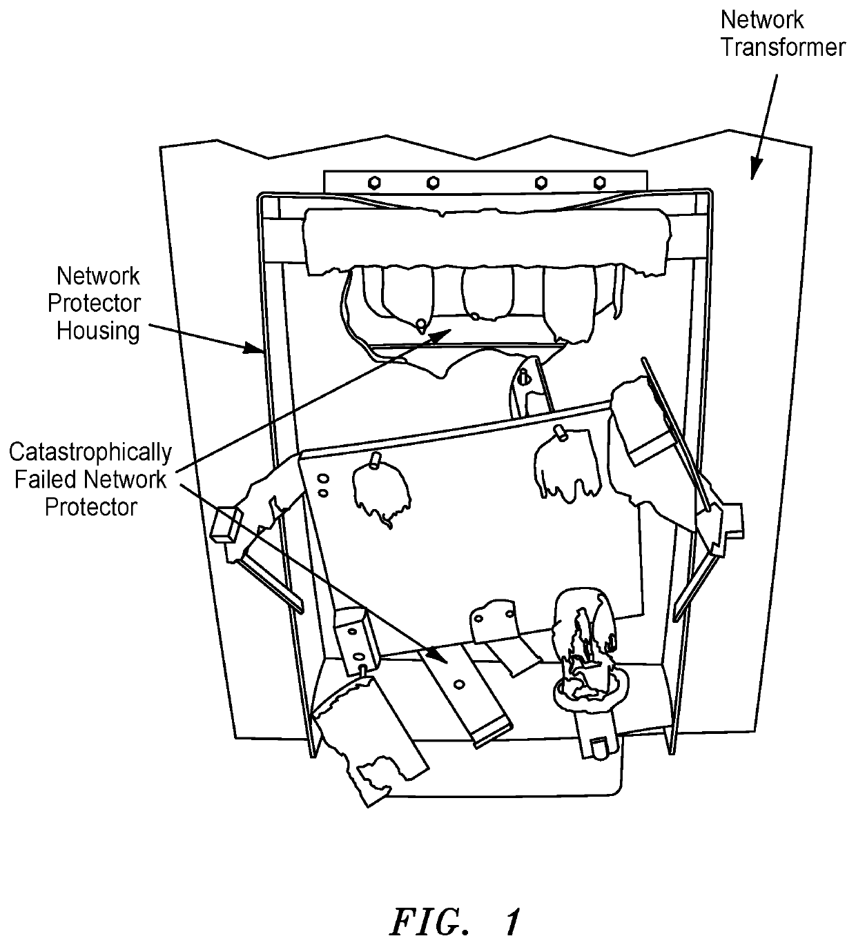
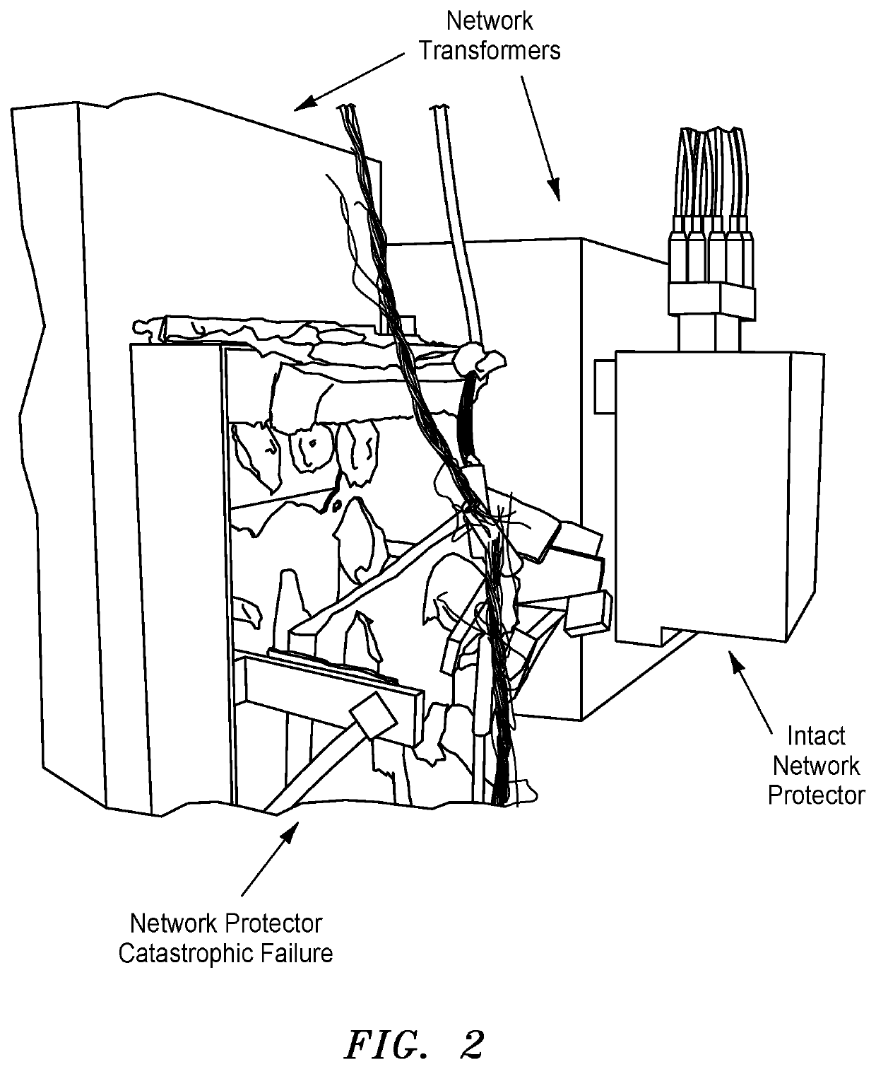
One of the failure scenarios with network protectors occurs when one fails to disengage from a network that is experiencing from an arcing fault wherein the average fault current is below the trip level for which the protector was set.
This failure mode is frequent when using prior art network protectors that may continue to feed power into a damaged circuit when there is an arcing fault.
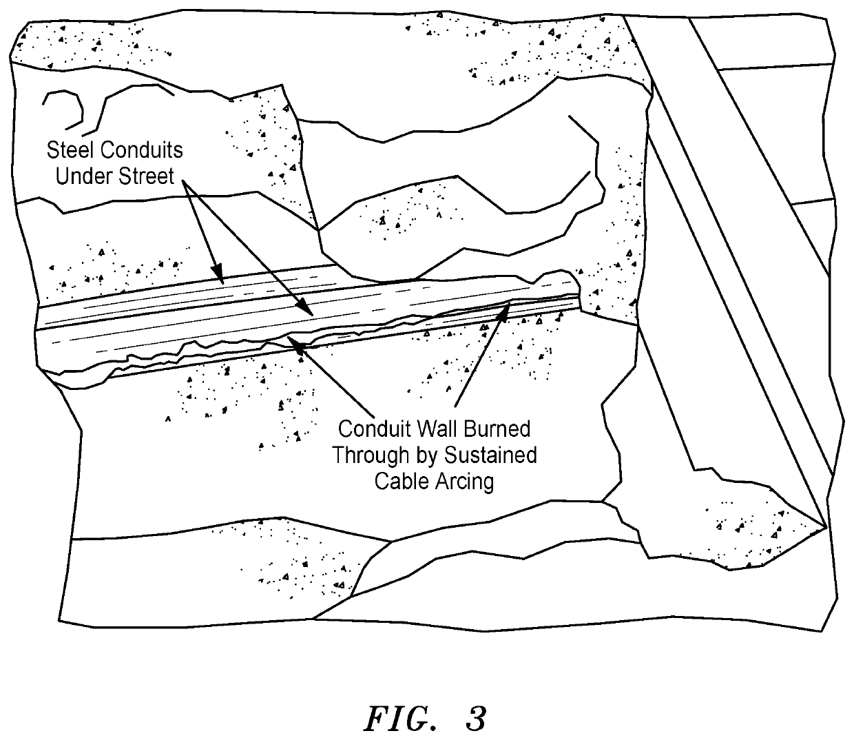
A failure of a feeder cable that resulted in a single phase short-circuiting to ground led to a series of events that resulted major losses, including electrical isolation of an entire city block for several days.
The vault fire could not be extinguished for several hours, leaving a heavy plume of sooty black smoke to be ingested into building ventilation systems, including a newly restored historic theater.
The fire was so intense that it destroyed the two-transformer vault.
In this instance, the network protector failed to detect the problem.
Because the network protector failed to respond to the short-circuited primary cable, and resulting high frequency arcing events (i.e., arcing fault), power flowed from the network back through the transformer, and into the shorted cable.
This caused one of the current paths inside the transformer to overheat and burn away, resulted in a horizontal breach through the steel tank, as shown in FIG. 6.
The cables feeding the transformer overheated and a fire ensued.
If oil vapor escaping from the transformer through the hole had accumulated and ignited, an explosion and major event would have followed.
Unfortunately, the network protectors of the prior art do not detect this type of situation, with particular respect to the individual high frequency, transient arcing events that, collectively define a ‘fault event’.
Though some designs have included a shrouded enclosure over the internal fuses, the fuses are not fully enclosed.
However, it is typically not the network protector manufacturers who undertake the external fusing.
Thus, there is often very limited clearance above a network protector that allows for installation of external fusing.
In many cases, this is impossible with the present generation of fuses.
Network protectors have historically suffered from reliability issues.
Most problematic is a failure to open during a high energy event.
This state of affairs is highly undesirable and entirely inconsistent with the operational performance of most switching equipment on electric utility systems.
This costly effort was undertaken due to chronic unreliability of the network protectors and the potentially and often dire consequences of a protector failing to operate correctly in a contingency situation.
Maintenance is also a critical issue for the present network protectors and there are many challenges involved.
Housing hardware issues may include:1) Corrosion of carbon steel enclosure;2) Corrosion and subsequent door bolt seizures / fractures; and3) Door gasket over-compression with resulting permanent deformation or cracking.
Internal corrosion concerns also exist and may include:1) Moisture penetration not typically obvious through the viewport; and2) Corrosion of sensitive components, often not apparent without detailed out-of-service inspections functionality testing failure.
Fundamental complaints regarding maintenance issues include:1) The complex mechanisms require specialized training for maintenance and troubleshooting, and repair;2) Most repairs and maintenance require a return to the vendor, which is expensive and forces spares to remain available;3) Too much maintenance is required, including:a. Arc chutes require inspection, cleaning, replacement;b. Electrical contacts require inspection for alignment and cleaning and resurfacing so that they are free of any pits, erosion, or surface asperities and, if necessary, replacement; andc. Mechanical components require lubrication;d.
As a result, it can be seen that crews often operate at a disadvantage when troubleshooting or conducting network equipment inspections, resulting in incomplete or insufficient inspections which can lead to eventual arcing faults and other conditions, resulting in subsequent damage or failure to the network transformer.
Failure to “open” during arcing fault conditions, such as serial, parallel, and ground;2) Corrosion of tank and subsequent loss of internal components;3) Non-corrosion related water penetration into tank and subsequent damage of internal components;4) Catastrophic rupture when closing into a network fault;5) Catastrophic rupture due to failure to open during extended arcing fault;6) Failure of mechanical charging system;7) Failure of electronic control components; and8) Component failure (i.e., mechanical, including pivots, guides, spring-charging drive, etc.)
The recloser is limited to switching operations.
Furthermore, in the event of natural disasters, such as an earthquake, electrical energy providers may need to discontinue service to various consumers of the utility's service, as described, for example, in U.S. Pat. Pub.
In other instances, the utility may shut off large sections of its distribution system if the damage is widespread.
However, doing so may interrupt utility service to areas that are not affected or to areas where the electric utilities are needed to aid with rescue and repair efforts.

Method used


Image

  • Network Service and Transformer Safety Protector
  • Network Service and Transformer Safety Protector
  • Network Service and Transformer Safety Protector

Examples


Embodiment Construction

[0132]To that end, in one embodiment, the present invention relates generally to a network service and transformer safety protector comprising:

[0133]A) a set of three low voltage, high current vacuum interrupters;

[0134]B) an insulated mechanical linkage that interconnects the three low voltage, high current vacuum interrupters to allow opening and closing by a single actuator;

[0135]C) a supervisory system comprising a supervisory controller and corresponding sensors within the network service and transformer safety protector and associated transformer;

[0136]wherein the network service and transformer safety protector is configured to:[0137]i) open the circuit for loss of power to the transformer or faults, either in the transformer or a primary feeder / primary switch serving the transformer,[0138]ii) automatically open the circuit whenever power flows form the secondary network through the transformer to the primary cable (reverse power flow), and[0139]iii) close the circuit whenever...


PUM

PropertyMeasurementUnit
voltageaaaaaaaaaa
voltageaaaaaaaaaa
voltageaaaaaaaaaa

Abstract

A network service and transformer safety protector on a secondary side of a network transformer tank system. The network service and transformer safety protector is positioned between the network transformer and a secondary network distribution system and is configured to connect and disconnect a transformer from the secondary network. The network service and transformer safety protector is attached to the outside of the transformer tank.

Description

CROSS-REFERENCE TO RELATED APPLICATIONS[0001]The present application claims the benefit of U.S. Provisional Application No. 62 / 829,413, the subject matter of which is herein incorporated by reference in its entirety.FIELD OF THE INVENTION[0002]The present invention relates generally to a network transformer unit that includes a network protector positioned on the secondary side of a network transformer for connecting / disconnecting the transformer to / from a secondary network power distribution system in response to predetermined electrical conditions on the primary feeder, network transformer, and the network.BACKGROUND OF THE INVENTION[0003]Medium voltage electrical power systems operated by electrical utility firms and the like typically include a large number of transformers, switches, circuit breakers, capacitor banks, and other major pieces of electrical equipment often interconnected through heavy duty cabling and switching devices for connecting and disconnecting the equipment...

Claims


Application Information

Patent Timeline
Patent Type & Authority Applications(United States)
IPC IPC(8): H02H7/04H01F27/40H02H1/00
CPCH01F27/402H02H7/04H02H1/0007H02H3/003H01H2033/66269H01H2033/66292H01H33/66261H01H33/6662H01H33/022H01H1/0206H01H1/0203
Inventor GROEGER, JOSEPH H.NORBERG, GARTHSEWELL, JEREMYDIX, LARRYSCHWARTZ, DANKLAPONSKI, BRIAN
Owner CARTE INT
Why Eureka
Try Eureka