
Multilayer radar-absorbing laminate for aircraft made of polymer matrix composite material with graphene nanoplatelets, and method of manufacturing same

a composite material and radar technology, applied in the direction of synthetic resin layered products, transportation and packaging, chemistry apparatus and processes, etc., can solve the problems of unsatisfactory results of liquid resin infusion technique, inability to ensure the electromagnetic properties of the component, and inability to achieve uniform and controllable electromagnetic properties, so as to achieve the effect of improving avoiding deformation of the structural or mechanical properties of the component, and ensuring the stability of the componen

Active Publication Date: 2021-01-07
LEONARDO SPA
View PDF2 Cites 9 Cited by
  • Summary
  • Abstract
  • Description
  • Claims
  • Application Information

AI Technical Summary

Benefits of technology

The patent describes a method for making an electromagnetic absorber that has good radar absorbency properties without compromising its mechanical or structural properties. The method involves using a three-layer structure, with a first layer made of a conductive material, a second layer made of a non-conductive material with a low loss factor, and a third layer made of a non-conductive material with a low loss factor and a thickness of less than a quarter of the wavelength associated with the central frequency of the desired absorption band. This third layer, called the impedance adapter, minimizes the reflection coefficient of the entire component in the desired absorption band by adapting its impedance to the wave impedance of the incident electromagnetic field. The method uses limited quantities of nanofillers, resulting in optimal radar absorbency properties without degrading the structural or mechanical properties of the component. The multi-layer sub-resonant structure of the electromagnetic absorber block allows for the combination of excellent electromagnetic properties with mechanical or structural ones due to the low content of nanoplatelets.

Problems solved by technology

It has been observed that by infusing the resin with inclusions of graphene nanoplatelets, the latter are not evenly distributed within the finished component.
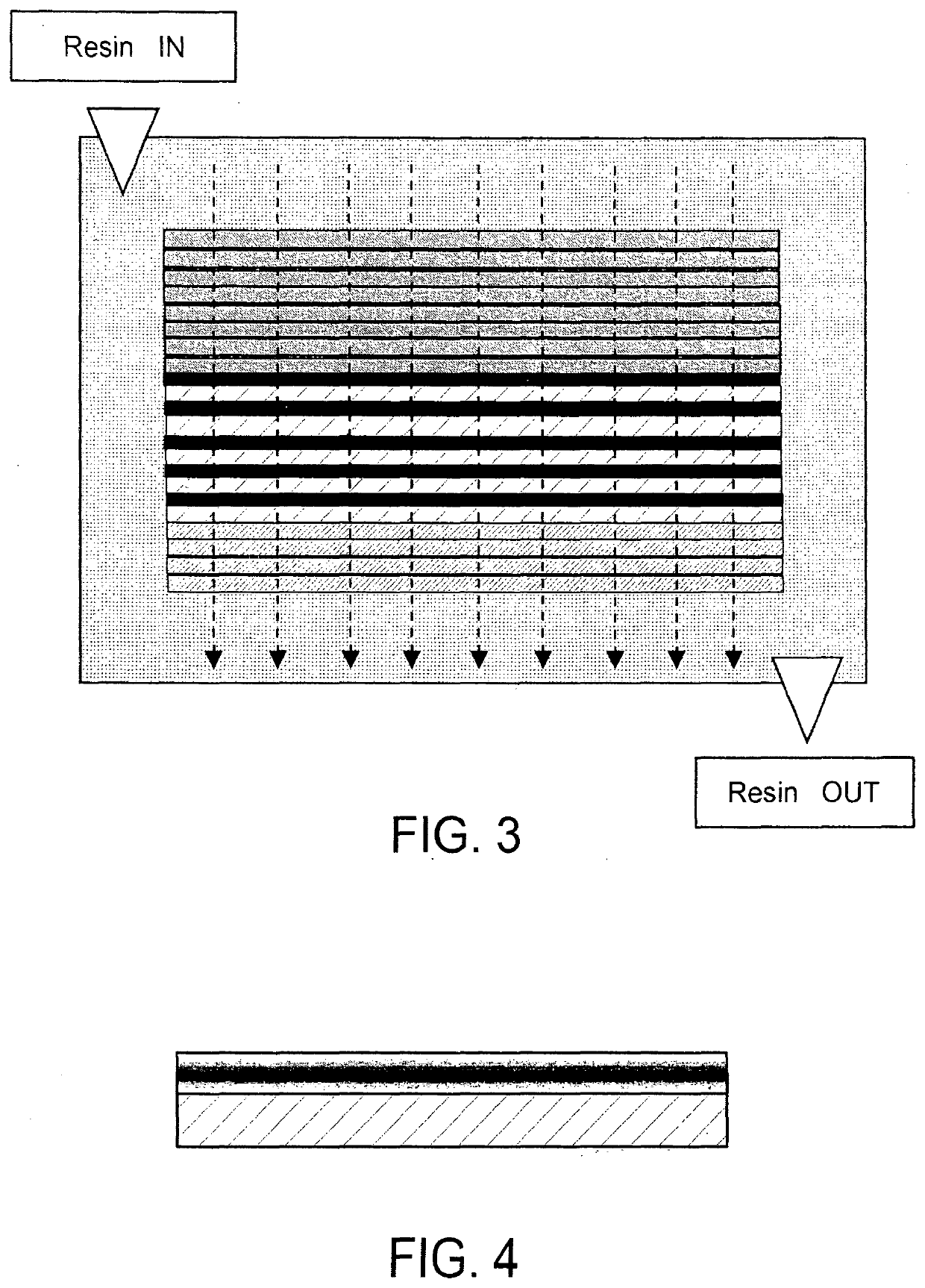
The “Liquid Resin Infusion” technique has not so far resulted in satisfactory results, because the resin containing the graphene, penetrating into the dry preform, is filtered by the fibers of the top sheets.
Consequently, a considerable part of the graphene remains accumulated in the top area of the preform, i.e. near the resin inlet points, thus not guaranteeing that the component has uniform and controllable electromagnetic properties.
However, the implemented methods reported so far have several disadvantages and limitations in terms of fabrication, performance, and practical applicability at industrial scale, because of high viscosity and inhomogeneous mechanical and electrical properties mainly arising from the formation of nanofiller agglomeration and non-uniform distribution.
The main difficulty of the process was to avoid formation of nanofiller agglomerates along the fiber texture.
Actually, the production of structural fibre-reinforced composite laminates with radar absorbing properties is still an open issue because in general satisfactory structural performances are achieved only at nanofiller concentration much lower than that corresponding to an improvement of EM absorption properties.
In previous studies, the authors have developed broadband EM absorbing panel made of graphene-filled epoxy or vinyl ester composite, but the produced prototypes of radar-absorbing material (RAM), did not perform as RAS.
However, none of these patent publications concern the manufacture of structural radar-absorbing materials, as typically the structural property is combined with obtaining electromagnetic shielding properties but not electromagnetic absorption.
In addition, the process is limited to composites with a polyamide matrix, which is a thermoplastic polymer.
It is known, however, that the sheet resistance values required to obtain electromagnetic shielding properties are well below the sheet resistance values required to obtain radar absorbency properties, which in effect are not considered in the patent.
However, the process described does not guarantee that the absorber will achieve broadband performance.
This results in low mechanical and electromagnetic performance due to the resulting poor adhesion of the nanoplatelets to the dry fiber.
The composites that may be obtained are not suitable for obtaining radar absorbency properties.

Method used


Image

  • Multilayer radar-absorbing laminate for aircraft made of polymer matrix composite material with graphene nanoplatelets, and method of manufacturing same
  • Multilayer radar-absorbing laminate for aircraft made of polymer matrix composite material with graphene nanoplatelets, and method of manufacturing same
  • Multilayer radar-absorbing laminate for aircraft made of polymer matrix composite material with graphene nanoplatelets, and method of manufacturing same

Examples


first embodiment

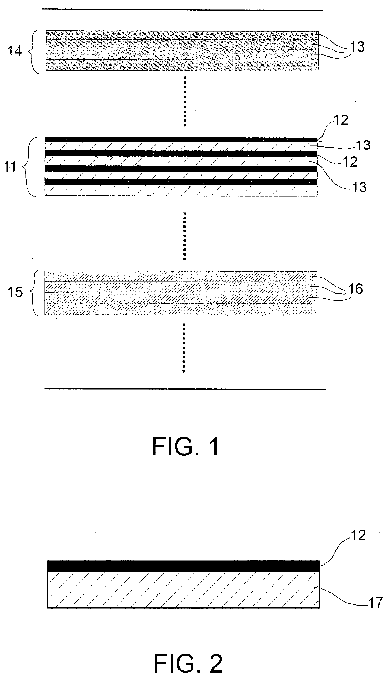
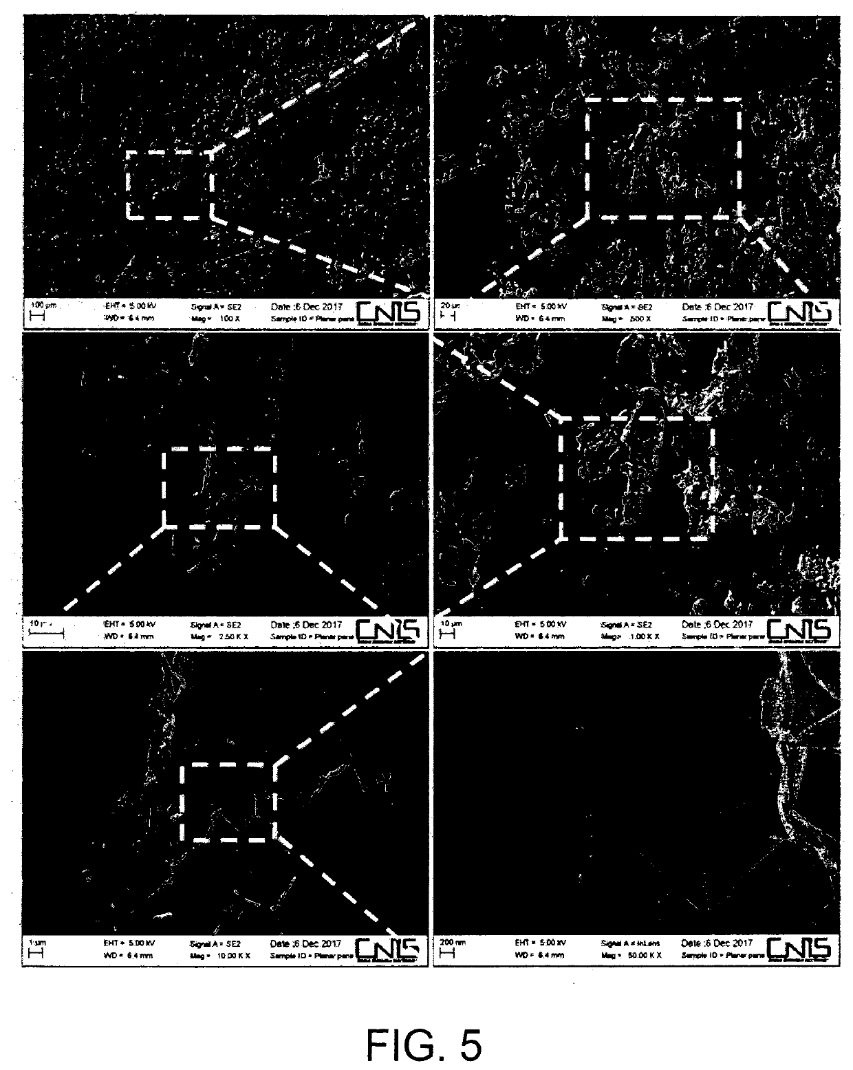
[0076]A production process of the second block 11“electromagnetic absorber” (FIG. 1) preferably consists of the following steps. a plurality of dry fiber sheets is prepared, on which graphene nanoplatelets are deposited. In the selection of the graphene-based nanomaterial, the nanomaterial used is preferably composed of graphene nanoplatelets having a thickness in the range of 2 nm to 100 nm, but less than the diameter of the fabric fibers of the fiber sheets and the distance between the bundles of weft and warp fibers. Such distance is generally between 100 nm and 10 microns, so that graphene nanoplatelets may penetrate between the weft and warp fiber bundles of the reinforcement fabric for the desired thickness. The thickness penetrated by the graphene nanoplatelets is linked to obtaining the desired electromagnetic properties of the second block, and is between 5 and 150 microns. Graphene nanoplatelets may be produced with the desired dimensional geometrical properties by applyi...

third embodiment

[0109]In the method for the manufacture of the second block, the prepreg sheets are made downstream of the dispersion of the solution containing the nanoparticles on the dry fiber with the same specifications and methods described, ensuring the same range of depth of penetration into the fibers as detailed above.

[0110]Regardless of the specific embodiment of the method, from the electromagnetic point of view, through the method according to the present invention and the contextual design of the lay-up, a “Jaumann Absorber” is essentially made with an impedance adapter wherein conductive layers (due to the penetration and uniform integration of graphene in the fiber and resin) and non-conductive layers (impregnated glass fiber) alternate. The proposed design is different from the standard version of the “Jaumann Absorber” known in the literature, through the insertion, according to an aspect of the present invention, of a suitably designed impedance adapter formed by a succession of ...


PUM

PropertyMeasurementUnit
Lengthaaaaaaaaaa
Fractionaaaaaaaaaa
Fractionaaaaaaaaaa

Abstract

A multilayer radar-absorbing laminate includes three juxtaposed blocks.A first electrically conductive block is arranged toward the inside of the aircraft in use.A second electromagnetic intermediate absorber block has a layer of electrically non-conductive fiber sheets is permeated by graphene-based nanoplatelets to achieve a periodic and electromagnetically subresonant layer, the conductive layers containing graphene nanoplatelets alternating with non-conductive layers.A third block of electrically non-conductive material is arranged towards the outside and forms part of the outer surface of the aircraft. The second block is produced by depositing on the fiber sheets a suspension of graphene nanoplatelets in a polymeric mixture, with controlled penetration of the graphene nanoplatelets into the fiber sheets. A plurality of dry fiber sheets sprayed with the suspension of graphene nanoplatelets is superimposed. An unpolymerized thermosetting synthetic resin is infused into a lay-up made of the first, second and third blocks. Afterwards, the thermosetting resin is polymerized.

Description

TECHNICAL SECTOR[0001]The present invention falls in the field of radar-absorbing aeronautical materials, i.e. materials with radio-frequency electromagnetic radiation absorption properties. In particular, the invention refers to radar-absorbing broadband multilayer laminates made of composite material laminated to a polymeric matrix containing graphene nanoplatelets. As an indication, the multilayer laminates described here may be used to make components or parts of the aircraft typically most exposed to radar radiation in the frontal sector, such as wing leading edges, nacelles, pylons, air intakes, or the so-called RCS hot spots, as well as curved panels of the fuselage, panels of wingboxes and tail empennages.PRIOR ART[0002]Graphite / graphene nanoplatelets (GNP) are known to be used as fillers, in variable concentrations, in the production of polymer matrix nanocomposites having controlled properties of radio-frequency complex dielectric permittivity. The multifunctional composit...

Claims


Application Information

Patent Timeline
IPC IPC(8): B32B27/12B29C70/88B29C70/02B32B17/04
CPCB32B27/12B29C70/882B82Y30/00B32B17/04B29C70/025H01Q17/00C08J5/005C08J5/04C08J5/06C08J5/08C08J2363/00B29C70/443C08J5/244C08J5/243C08J5/249B32B2264/302B32B2264/201B32B2262/106B32B2264/108B32B2307/202B32B2307/212B32B2605/18B82Y40/00
Inventor PISU, LUIGIIAGULLI, GIANNISARTO, MARIA SABRINAMARRA, FABRIZIOLECINI, JULIANTAMBURRANO, ALESSIO
Owner LEONARDO SPA
Learn More