Glass windows for lidar applications

a technology of glass windows and lidar windows, applied in the field of glass windows, can solve the problems of affecting the reflected light has to pass enormously, and the service life of the polymer window is often increased, so as to achieve the effect of reducing reflection losses and ensuring the optical performance and reliability of the system

Pending Publication Date: 2021-01-28
SCHOTT AG
View PDF5 Cites 8 Cited by
  • Summary
  • Abstract
  • Description
  • Claims
  • Application Information

AI Technical Summary

Benefits of technology

[0118]For this purpose, the method may comprise the further step of applying one or more antireflection layer/s (AR layer) onto the glass window, in particular onto the outer side of the glass window. The application of the antireflection layer/s may lead to the fact that the composite consisting of the glass window and the antireflection layer/s becomes highly transparent in the near infrared (NIR), in particular for the intended working wavelengths. For example, the composite may have a reflection degree of lower than 4%, preferably lower than 3%, preferably lower than 2%, in particular for working wave lengths in the near infrared region of the spectrum (NIR), for example for working wavelengths of 905 nm, 940 nm or 1550 nm. In other words, the antireflection layer/s can reduce reflection losses for light in the working wavelength range at the air/glass interface and thus lead to a higher transmission of light in the working wavelength range. The applied antireflection la

Problems solved by technology

However, LiDAR windows of polymer materials have disadvantages with respect to their service life and reliability.
Polymer windows often have an increased susceptibility to scratches due to their low scratch resistance.
Scratched surfaces through which light to be reflected and reflected light have to pass enormously compromise the optical performance and reliability of the system, in particular by reduction of light, misallocation of light onto false pixels, scattering and reduction of the signal/noise ratio.
A further disadvantage of prior art polymer windows is a poor adhesion of additional layers on the polymer windows.
Due to the poor adhesive properties of the polymer windows often these additional layers are at least partially detached which reduces the signal strengths and thus the signal/noise ratios.
In addition, locally detached coatings result in undesired jumps of the signal strengths.
Furthermore, polymer windows have a low and often insufficient environmental stability.
Such a discoloration results in reduction of signal strengths.
Polycarbonate, for example, is relatively UV stable, but nevertheless user

Method used


Image

  • Glass windows for lidar applications
  • Glass windows for lidar applications

Examples


Embodiment Construction

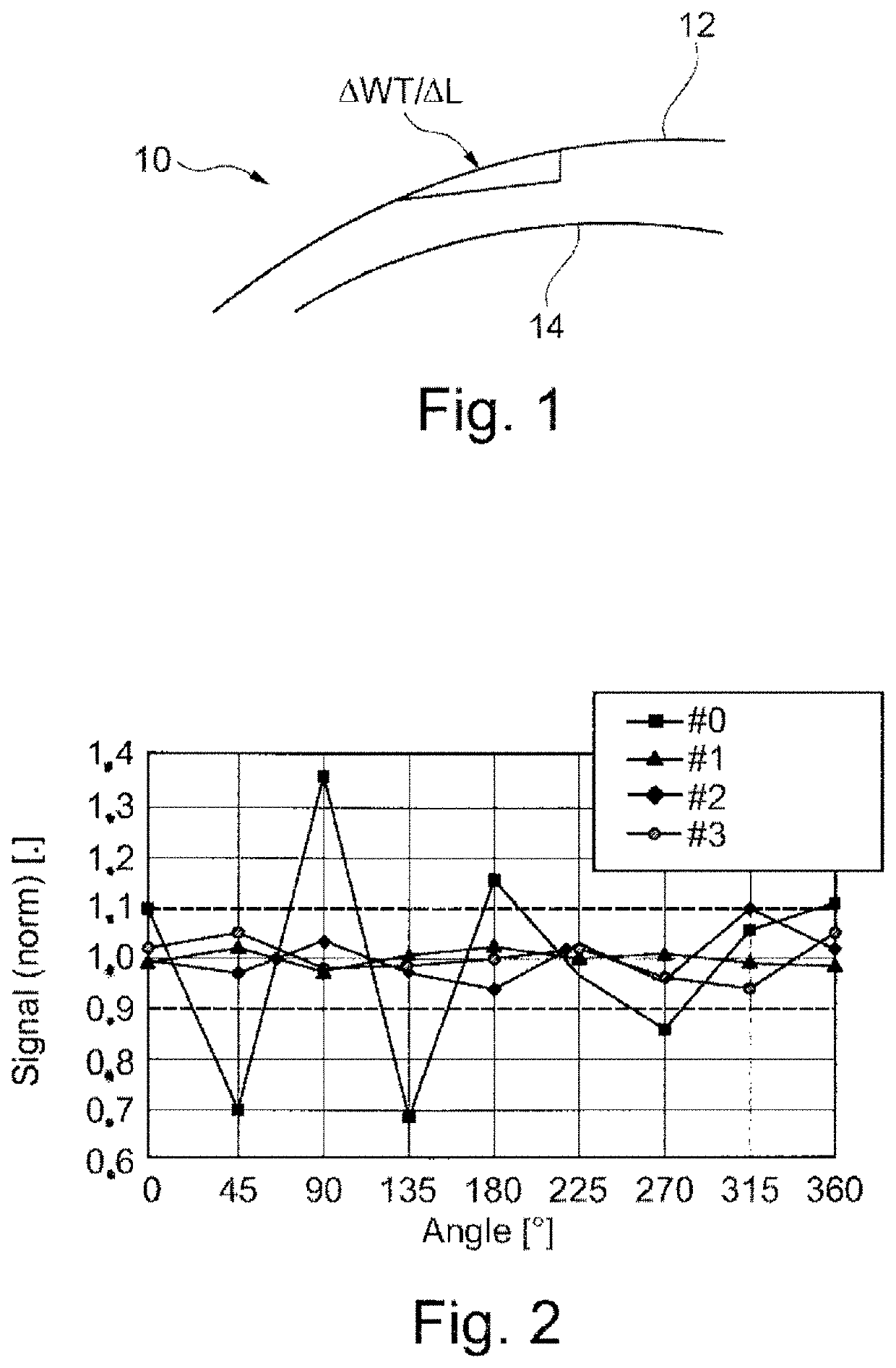
mm and a target value of the wall thickness of 2.0 mm. A second example of a further embodiment of a glass window according to the present disclosure has the form of a complete ring (360°) with a target value of the outer diameter of 135 mm and a target value of the wall thickness of 2.0 mm. In both examples, the glass window is intended for a use in a LiDAR system with a laser having a working wavelength of 905 nm and has the following measures and parameters:

Properties and parameter values of the glassring according to the present disclosureFirst exampleSecond exampleOD0 or 2R0 [mm]85.00135.00OD [mm] with WT = constant85.00 ± 1.00135.00 ± 1.50OD [mm] with ID = constant85.00 ± 0.20135.00 ± 0.30WT [mm] with ID = constant 2.00 ± 0.10 2.00 ± 0.15WT [mm] with OD = constant 2.00 ± 0.10 2.00 ± 0.15ID [mm] with OD = constant81.00 ± 0.20131.00 ± 0.30n1.5089 ± 0.04 1.5089 ± 0.04RMS roughness [nm](surfaces of the inner andouter sides)max. SEG for length scales0.00050.0004between 0.1 mm and 1...


PUM

PropertyMeasurementUnit
Lengthaaaaaaaaaa
Lengthaaaaaaaaaa
Fractionaaaaaaaaaa

Abstract

The disclosure relates to a glass window for optical systems, in particular for LiDAR systems, in which the glass window has a curved form. For length scales between 0.1 mm and 15 mm, at least 50% of the area of the glass window has a geometrical slope error SEG for which the following is true: SEG<−2.3·10−6·2·R0[1/mm]+7.3·10−4.

Description

CROSS-REFERENCE TO RELATED APPLICATIONS[0001]The present application claims priority to European Patent Application No. EP 19 18 7909.7, filed Jul. 23, 2019, European Patent Application No. EP 19 21 3558.0, filed Dec. 4, 2019, and European Patent Application No. EP 20 16 1338.7, filed Mar. 5, 2020, each of which is incorporated herein by reference.SUMMARY OF THE DISCLOSURE1. Field of the Disclosure[0002]The present disclosure relates to a glass window for optical systems and instruments, in particular for LiDAR systems (LiDAR: light detection and ranging). Furthermore, the disclosure relates to a LiDAR system with such a glass window as well as a method for the manufacturing of such a glass window.2. Description of the Related Art[0003]LiDAR (abbreviation for “light detection and ranging”) or also LaDAR (abbreviation for “laser detection and ranging”) is a method for optical measurement of distance and velocity by means of laser light, in the following referred to as LIDAR. For that...

Claims


Application Information

Patent Timeline
IPC IPC(8): G01S7/481G02B5/20G02B1/11
CPCG01S7/4813G01S7/4817G02B1/11G02B5/208G01S7/4814E06B9/24E06B7/28E06B3/30E06B2009/2405G01S17/931C03C4/10C03C17/00C03C3/091C03C4/02B32B17/10
Inventor SCHULTZ, NIKOLAUSEICHHORN, BORISLENTES, FRANK-THOMASTHOMAS, JENS ULRICHPLAPPER, VOLKER
Owner SCHOTT AG
Why Eureka
Try Eureka