Method for coating thermal/environmental barrier coating

a technology of thermal/environmental barrier and coating, which is applied in the direction of superimposed coating process, vacuum evaporation coating, coating, etc., can solve the problems of sharp deterioration of the surface stability of sic ceramic matrix composite, increase in the temperature of fuel gas in the aero-engine, and increase in the surface temperature of the hot-end components of the high-pressure turbin

Inactive Publication Date: 2021-02-18
GUANGDONG INST OF NEW MATERIALS
View PDF0 Cites 1 Cited by
  • Summary
  • Abstract
  • Description
  • Claims
  • Application Information

AI Technical Summary

Problems solved by technology

The development of a new generation of aero-engine with high thrust-weight ratio will inevitably lead to an increase in the temperature of fuel gas in the aero-engine, which in turn will increase the surface temperature of the hot-end components of the high-pressure turbine.
Under the working environment of the engine, many factors, such as high temperature, corrosive media, fuel gas scour, and complex stress environment, interact with each other, and the surface stability of SiC ceramic matrix composite is deteriorated sharply, which has become one of the main factors restricting its application to hot-end components of aero-engine.
The main problem of the early first-generation mullite environmental barrier coatings was that the coatings would produce more cracks during use, so that the corrosive substances could infiltrate along the cracks and contact the substrate, causing damage to the substrate.
The densities of the two kinds of mullite are different, and thermal stress will be generated in the process of conversion, which will cause cracks.
The adhesive force of the improved mullite environmental barrier coating was enhanced, and cracks in the coating were effectively controlled, but the surface stability of the silicon-based non-oxide ceramic with the mullite environmental barrier coating was still insufficient.
Therefore, the mullite environmental barrier coating has a poor ability to resist water vapor erosion.
The environmental barrier coating of mullite +YSZ system significantly reduced the volatilization of SiO2 during the initial service, but the durability of this protective effect was insufficient.
When the coating was used in an environment containing water vapor at 1300° C. for about 100 hours, the coating would undergo accelerated oxidation failure.
The analysis showed that such accelerated oxidation failure has a lot to do with the cracks generated during the service process of the coating.
The generation of thermal stress is unavoidable in the process of cold and thermal cycles, and thus the cracks are induced.
The first-generation environmental barrier coatings were far from being able to be applied in the engine environment due to the insufficient long-term stability of the coating materials and the formation of cracks during use.
The disadvantage of the second-generation environmental barrier coatings is their lower maximum use temperature.
At higher operating temperatures, although the SiO2 activity in BSAS is lower than that of mullite, the surface stability of the coating still cannot meet the requirements of engine design.
And BSAS has poor chemical compatibility with SiO2 at high temperatures.
Such glass phase has a relatively low molten temperature zone of about 1300° C. The presence of the glass phase reduces the bonding force of the coating, which may cause early failure of the coating.

Method used


Image

  • Method for coating thermal/environmental barrier coating
  • Method for coating thermal/environmental barrier coating

Examples


embodiment 1

[0073]The method for coating an environmental barrier coating provided by this embodiment includes the following operating steps:

[0074]preparing a Si coating, a mullite coating, and a Yb2SiO5 coating on the surface of silicon carbide-based composite substrate by using air plasma spraying, with the coatings successively having thicknesses of 50 μm, 50 μm and 80 μm;

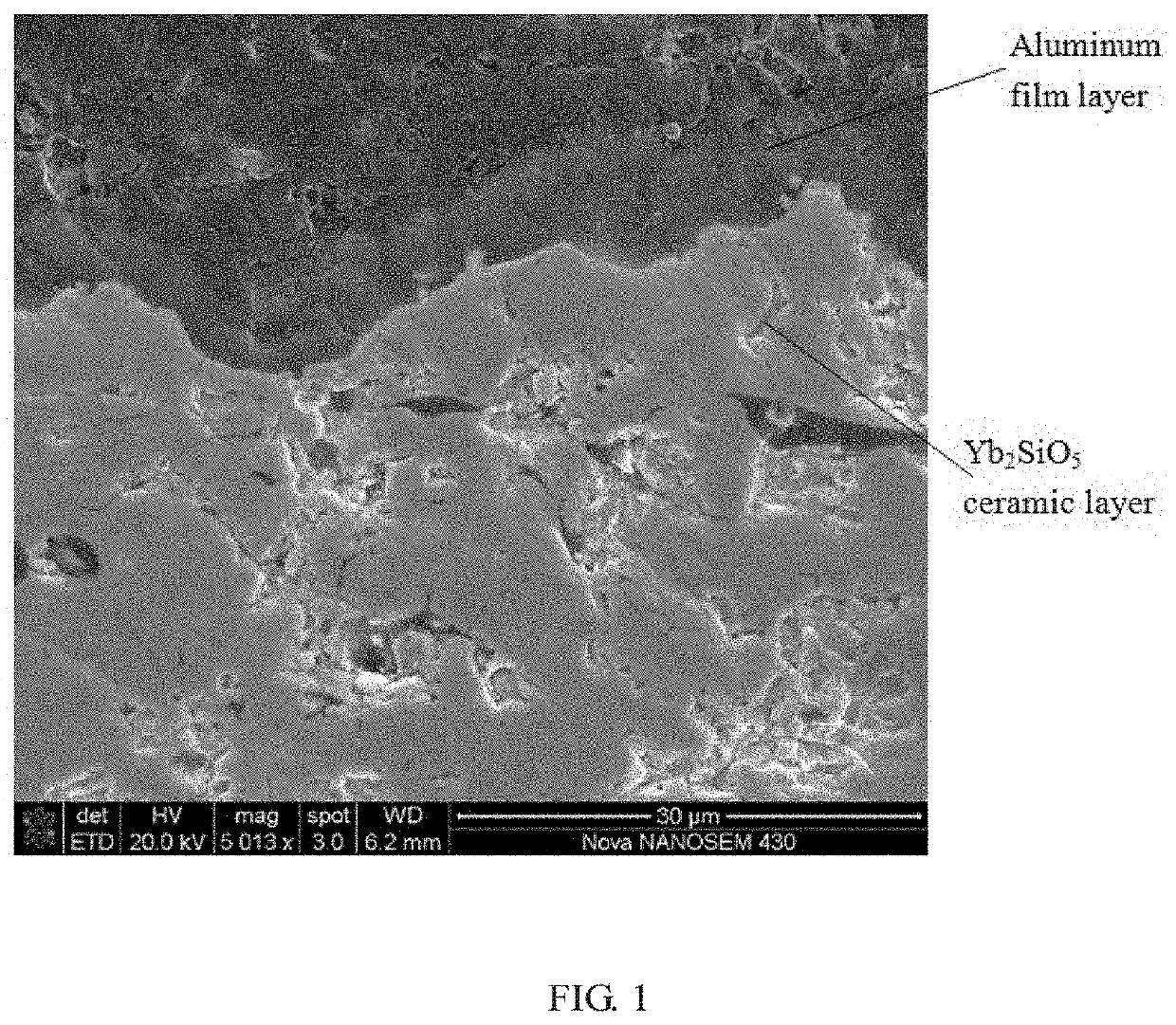
[0075]preparing an aluminum film layer with a thickness of 3μm on the surface of the Yb2SiO5 coating by using the magnetron sputtering, wherein the conditions of the magnetron sputtering are as follows: a magnetron target current of 3 A and a bias voltage of 150 V;

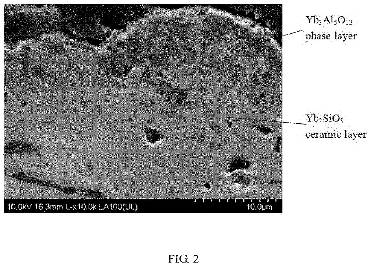
[0076]heat treating the Yb2SiO5 coating deposited with the aluminum film layer, wherein the conditions of heat treatment are as follows: 800° C. kept for 2 h, 1300° C. kept for 24 h, a temperature raising rate of 5° C. / min, and a vacuum oxygen partial pressure less than 2×10⁻³ P; and

[0077]cooling to a room temperature, to obtain the environmental barrier coating o...

embodiment 2

[0078]The method for coating an environmental barrier coating provided by this embodiment includes the following operating steps:

[0079]preparing a Si coating, a mullite coating, and a Yb2SiO5 coating on the surface of silicon carbide-based composite substrate by using plasma spraying-physical vapor deposition, with the coatings successively having thicknesses of 50 μm, 50 μm and 80 μm;

[0080]preparing an aluminum film layer with a thickness of 3 μm on the surface of the Yb2SiO5 coating by using the magnetron sputtering, wherein the conditions of the magnetron sputtering are as follows: a magnetron target current of 3 A and a bias voltage of 150 V;

[0081]heat treating the Yb2SiO5 coating deposited with the aluminum film layer, wherein the conditions of heat treatment are as follows: 700° C. kept for 2 h, 1300° C. kept for 24 h, a temperature raising rate of 10° C. / min, and a vacuum oxygen partial pressure less than 2×10⁻³ Pa; and

[0082]cooling to a room temperature, to obtain the enviro...

embodiment 3

[0083]The method for coating an environmental barrier coating provided by this embodiment includes the following operating steps:

[0084]preparing a Si coating, a mullite coating, and a Yb2SiO5 coating on the surface of silicon carbide-based composite substrate by using plasma spraying-physical vapor deposition, with the coatings successively having thicknesses of 50 μm, 50 μm and 80 μm;

[0085]preparing an aluminum film layer with a thickness of 2 μm on the surface of the Yb2SiO5 coating by using the magnetron sputtering, wherein the conditions of the magnetron sputtering are as follows: a magnetron target current of 3 A and a bias voltage of 150 V;

[0086]heat treating the Yb2SiO5 coating deposited with the aluminum film layer, wherein the conditions of heat treatment are as follows: 700° C. kept for 2 h, 1350° C. kept for 20 h, a temperature raising rate of 10° C. / min, and a vacuum oxygen partial pressure less than 2×10⁻³ Pa; and

[0087]cooling to a room temperature, to obtain the enviro...


PUM

PropertyMeasurementUnit
thicknessaaaaaaaaaa
temperatureaaaaaaaaaa
bias voltageaaaaaaaaaa

Abstract

The present disclosure discloses a method for coating an environmental barrier coating, comprising: coating an aluminum film layer on a surface of a rare earth silicate ceramic layer, and heat treating the aluminum film layer to form a rare earth aluminate phase at least in pores of a side of the rare earth silicate ceramic layer facing the aluminum film layer. An environmental barrier coating prepared by the above method is also disclosed.

Description

CROSS-REFERENCE TO RELATED APPLICATIONS[0001]The present application claims priority to Chinese Patent Application No. 201910744227.X, filed with the Chinese Patent Office on Aug. 13, 2019, entitled “Environmental Barrier Coating, Coating method and Application thereof”, which is incorporated herein by reference in its entirety.TECHNICAL FIELD[0002]The present disclosure relates to the technical field of the surface treatment of ceramic coatings, and in particular, to a method for coating a thermal / environmental barrier coating.BACKGROUND ART[0003]The development of a new generation of aero-engine with high thrust-weight ratio will inevitably lead to an increase in the temperature of fuel gas in the aero-engine, which in turn will increase the surface temperature of the hot-end components of the high-pressure turbine. The surface temperature of the hot-end components of the aero-engine with high thrust-weight ratio will reach above 1400° C., far exceeding the temperature range that ...

Claims


Application Information

Patent Timeline
Patent Type & Authority Applications(United States)
IPC IPC(8): C23C14/18C23C14/35C23C14/02C23C14/58C23C28/00C23C14/28
CPCC23C14/18C23C14/35C23C14/28C23C14/5806C23C28/324C23C14/024C23C14/185C23C28/322C23C28/345C23C4/11C23C4/134C23C4/10C23C28/321C23C28/3455C23C4/04C23C4/18
Inventor ZHANG, XIAOFENGWANG, CHAODENG, CHUNMINGLIU, MINDENG, ZIQIANNIU, SHAOPENGMAO, JIEDENG, CHANGGUANGZHOU, KESONG
Owner GUANGDONG INST OF NEW MATERIALS
Why Eureka
Try Eureka