Polycarbonate resin composition

a polycarbonate resin and composition technology, applied in the field of polycarbonate resin composition, can solve the problems of low brightness, polycarbonate resins are more likely to suffer from problems such as yellowing than pmma, and achieve excellent anti-static properties and surface appearance, improve transmittance and hue, and improve the effect of transmittance and yellowing degr

Active Publication Date: 2021-03-25
MITSUBISHI ENG PLASTICS CORP +1
View PDF0 Cites 0 Cited by
  • Summary
  • Abstract
  • Description
  • Claims
  • Application Information

AI Technical Summary

Benefits of technology

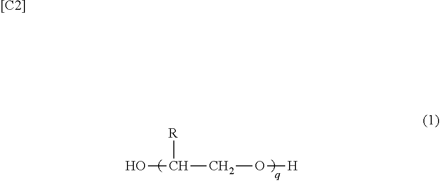
[0007]However, blending polyethylene glycol, poly(2-methyl)ethylene glycol, or the like, in a thermoplastic resin such as a polycarbonate resin is a known feature, and PTL 4 discloses a γ-radiation-resistant polycarbonate resin containing same, and PTL 5 discloses a thermoplastic resin composition which contains PMMA or the like and which exhibits excellent anti-static properties and surface appearance.
[0008]In addition, PTL 6 proposes improving transmittance and hue by blending a polyalkylene glycol constituted from a straight chain alkyl group. An improvement in transmittance and degree of yellowing (yellow index: YI) can be seen by blending polytetramethylene ether glycol.
[0009]Furthermore, PTL 7 discloses a method for producing a polycarbonate copolymer by using a diol obtained by diesterification of a polyalkylene glycol as a raw material (comonomer), but in this polycarbonate copolymer, the diol obtained by diesterification of a polyalkylene glycol is unstable, and the polycarbonate copolymer is inadequate in terms of impact resistance and is also poor in terms of hue and thermal discoloration resistance.
[0010]In recent years in particular, optical components such as light guide plates in hand-held terminals such as smart phones and tablets have become both thinner and larger at a remarkable rate, and there have been demands for higher barrel temperatures and higher injection speeds for molding light guide plates. As a result, the amount of gas generated at the time of molding has increased and problems have occurred, such as mold contamination readily occurring. Therefore, resin compositions used for molding such products require not only excellent optical characteristics, but also low mold contamination caused by gas generation during high temperature injection molding, and excellent impact resistance.

Problems solved by technology

Polycarbonate resins exhibit excellent mechanical properties, thermal properties, electrical properties and weather resistance, but exhibit lower light transmittance than PMMA and the like, and problems such as low brightness therefore occur in cases where a planar light source is constituted from a polycarbonate resin light guide plate and a light source.
In addition, there have been demands in recent years for a reduction in differences in chromaticity between an incident part of a light guide plate and a position distant from the incident part, but polycarbonate resins are more likely to suffer from problems such as yellowing than PMMA.
However, the method disclosed in PTL 1 achieves an improvement in hue by adding the acrylic resin, but cannot increase light transmittance and brightness due to white turbidness occurring, and adding the alicyclic epoxy compound can improve transmittance, but no improvement in hue has been confirmed.
Furthermore, PTL 7 discloses a method for producing a polycarbonate copolymer by using a diol obtained by diesterification of a polyalkylene glycol as a raw material (comonomer), but in this polycarbonate copolymer, the diol obtained by diesterification of a polyalkylene glycol is unstable, and the polycarbonate copolymer is inadequate in terms of impact resistance and is also poor in terms of hue and thermal discoloration resistance.
As a result, the amount of gas generated at the time of molding has increased and problems have occurred, such as mold contamination readily occurring.

Method used


Image

  • Polycarbonate resin composition
  • Polycarbonate resin composition
  • Polycarbonate resin composition

Examples


production example 1

rbonate Copolymer (B11)

[0186]An amount corresponding to 75 mass % of “PTMG650” available from Mitsubishi Chemical Corporation (Mw: 1,950) as polytetramethylene glycol (hereinafter abbreviated to PTMG), an amount corresponding to 25 mass % of bisphenol A (hereinafter abbreviated to BPA) and diphenyl carbonate (hereinafter abbreviated to DPC) at a molar ratio of 1.05 relative to the amount of diol were added to a polymerization apparatus equipped with a 1 L five-mouthed flask. The pressure in the system was lowered to 0.13 kPaA or less, drying was carried out for 1 hour, and tetramethyl ammonium hydroxide (TMAH.5H2O) was then added as a catalyst at a quantity of 10,000 μmol relative to 1 mole of the diol. The pressure in the system was lowered to 0.13 kPaA or less, drying was carried out for 15 minutes so as to remove water derived from the catalyst, and the pressure inside the polymerization apparatus was then restored with nitrogen. At the point when the pressure-restored polymeriza...

production example 2

rbonate Copolymer (B12)

[0188]Polymerization was carried out in the same way as in Production Example 1, except that “PTMG1000” available from Mitsubishi Chemical Corporation (Mw: 3,450) was used as the PTMG and the heating / depressurization program shown in Table 1 was used.

[0189]The proportions by mass of a bisphenol A (BPA) constituent component and a polytetramethylene glycol (PTMG) constituent component in the obtained polycarbonate copolymer (B12) were 25 mass % of BPA and 75 mass % of PTMG, and the polycarbonate copolymer had a weight average molecular weight (Mw) of 10,300.

production example 3

rbonate Copolymer (B13)

[0190]Polymerization was carried out in the same way as in Production Example 1, except that “PTMG1500” available from Mitsubishi Chemical Corporation (Mw: 5,400) was used as the PTMG and the heating / depressurization program shown in Table 1 was used.

[0191]The proportions by mass of a bisphenol A (BPA) constituent component and a polytetramethylene glycol (PTMG) constituent component in the obtained polycarbonate copolymer (B13) were 25 mass % of BPA and 75 mass % of PTMG, and the polycarbonate copolymer had a weight average molecular weight (Mw) of 9,400.


PUM

PropertyMeasurementUnit
temperatureaaaaaaaaaa

Abstract

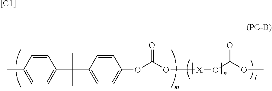
A polycarbonate resin composition containing 0.1 to 10 parts by mass of a polycarbonate copolymer (B) having carbonate bonding between (B1) bisphenol A and a (B2) polyalkylene glycol and 0.005 to 0.5 parts by mass of a phosphorus-containing stabilizer (C) relative to 100 parts by mass of a polycarbonate resin (A).

Description

TECHNICAL FIELD[0001]The present invention relates to a polycarbonate resin composition, and more specifically relates to a polycarbonate resin composition which exhibits excellent impact resistance, has a good hue and causes very little gas generation and mold contamination at the time of molding; and a molded article obtained by molding the composition.BACKGROUND ART[0002]Liquid crystal display devices used in personal computers, mobile telephones, and the like, include planar light source devices in order to meet demands for reduced thickness and weight, reduced energy consumption and higher resolution. In addition, such planar light source devices are devices in which one surface is provided with a light guide plate having a wedge-shaped cross section having a uniform slanted surface or a panel-shaped light guide plate in order to achieve the effect of uniformly and efficiently guiding incident light to the liquid crystal display side. In addition, a light-scattering function is...

Claims


Application Information

Patent Timeline
Patent Type & Authority Applications(United States)
IPC IPC(8): C08G64/16C08G64/30C08K5/526C08K5/1525C08L69/00
CPCC08G64/1608C08G64/30C08L2205/025C08K5/1525C08L69/00C08K5/526C08K5/1515C08K5/49G02B1/04C08G64/183C08K5/527
Inventor TOMITA, KEISUKEHARADA, HIDEFUMIISOBE, TAKEHIKOSHIMOKAWA, KEISUKETAGUCHI, JUGO
Owner MITSUBISHI ENG PLASTICS CORP
Why Eureka
Try Eureka