Electrodes comprising three-dimensional heteroatom-doped carbon nanotube macro materials

a carbon nanotube and macro-material technology, applied in the field of electrochemical devices comprising three-dimensional heteroatomdoped carbon nanotube macro-materials, and batteries and capacitors, can solve the problems of reducing the useful life of ion batteries, limiting the effective life cycle, and low yield of mechanical exfoliation, so as to achieve excellent physical and chemical properties, long useful life, and electrical capacity.

Pending Publication Date: 2021-09-02
3D NANO BATTERIES LLC
View PDF4 Cites 2 Cited by
  • Summary
  • Abstract
  • Description
  • Claims
  • Application Information

AI Technical Summary

Benefits of technology

[0013]Using this ratio of carbon, boron, and metal catalyst, it is possible to form a highly porous, three dimensional network of boron-doped carbon nanotubes, which are electrically conductive, and offer excellent physical and chemical properties. When partially filled with lithium metal (anode) or lithium salts (cathode), the electrodes have longer useful lifetimes, before dendrite formation, than conventional lithium batteries. Further, in some embodiments, the electrical capacity significantly exceeds that of conventional lithium batteries.
[0014]In some embodiments, electrodes produced using the CNT foam material greatly enhance the electrode's power density and final capacitor components resulting from embedding active materials into the foam structure. A capacitor having a submicron-scale, three-dimensional porous conductive foam structure as an anode, separated from the counter electrode material, that fills all or part of the void space of the porous foam structure, can significantly increase the power density of the final energy storage devices.

Problems solved by technology

One concern is that the lithium ion batteries degrade over time, limiting their effective life cycle.
However, in order to show its excellent properties, graphene needs to be exfoliated to atom layer thickness, and such mechanical exfoliation has a low yield.
However, the reduction method using a high-temperature reducing gas is not suitable for mass production and increases the unit cost of production.

Method used


Image

  • Electrodes comprising three-dimensional heteroatom-doped carbon nanotube macro materials
  • Electrodes comprising three-dimensional heteroatom-doped carbon nanotube macro materials
  • Electrodes comprising three-dimensional heteroatom-doped carbon nanotube macro materials

Examples


example 1

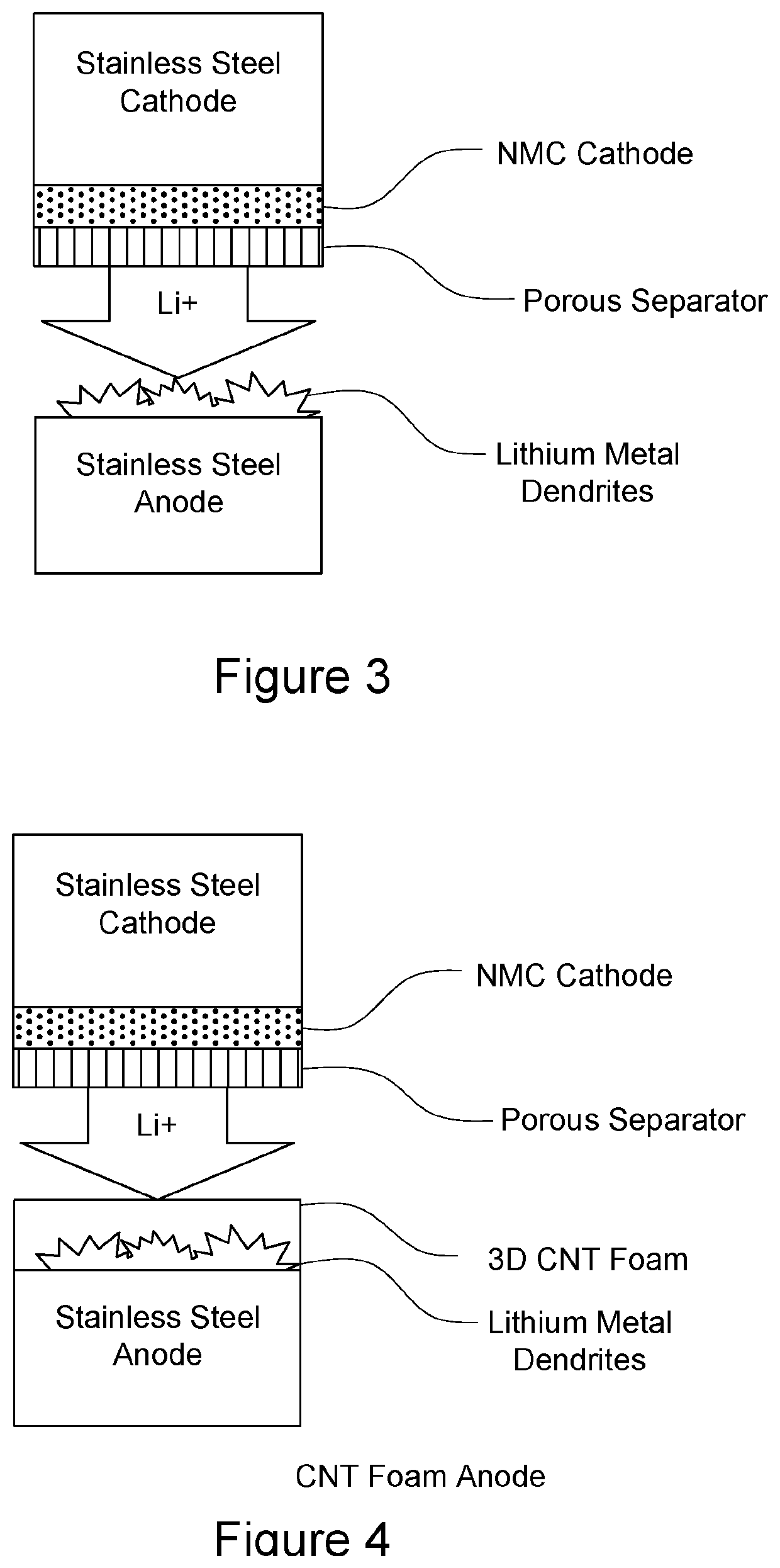
n / Comparison of Anode Performance Between Stainless Steel and 3D Foam Anodes

[0272]Development Rationale

[0273]The following examples was carried out on a three dimensional nanotube material prepared according to the teachings of U.S. Ser. No. 13 / 424,185.

[0274]The “Holy Grail” of the lithium battery industry is to create a practical lithium “metal” battery. Lithium metal has the highest energy density of any anode for both volumetric and gravimetric energy densities. Graphite as an anode material has ˜360 mAhr / g energy capacity. Lithium metal has an energy density of 3860 mAhr / g. This is not a 10-fold increase in the battery performance, rather a 10-fold increase in the anode performance. Since the anode is 30-50% of a cell volume / mass, the increase in battery performance is more in line with a 2- or 3-fold increase in battery performance, which represents a significant improvement in battery performance.

[0275]The goal is to construct a lithium metal battery structure with the 3D-CNT ...

example 2

n of 3D CNF Foams in Half-Cell Configurations Vs. Lithium Metal

[0340]The objective of this set of tests was to measure fundamental performance of the 3D CNT Foam in a half-cell configuration versus lithium metal.

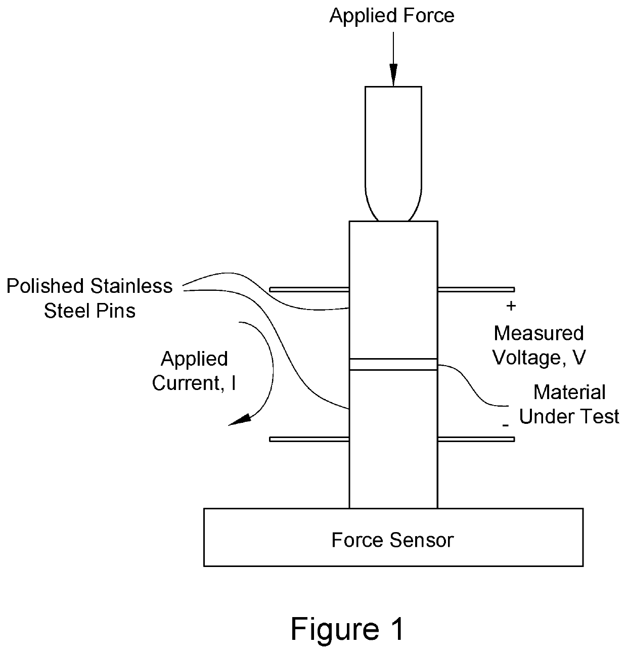
[0341]The configuration of the test in a Swagelok cell is shown in FIG. 3. Current was controlled at a specified rate and the voltage profile of the cell was measured during this current flow. The lithium disk supplied as much Li as the opposing electrode can use. This allowed the anode to reach full capacity without any lithium metal plating.

[0342]To be clear, intercalation of Li+ ions cannot penetrate the side-wall of a fully intact nanotube. Similar to graphite, the Li+ ion can only penetrate at the edges of the graphene structure, whether planar or cylindrical. If there is damage at some point in the nanotube wall (branching, dislocations . . . ) then Li+ ions might have the ability to penetrate into the nanotube wall. This is also true in connection with concentric ring...

example 3

n of 3D CNF Foams in Full-Cell Configurations vs. Lithium Metal

[0366]The objective of this set of tests was to measure fundamental performance of the 3D CNT Foam in a full-cell configuration versus lithium metal.

[0367]The 3D CNF data is based on the same LCO cathode or higher performance NCM variants. To get the whole 100% increase in capacity, this compares conventional LCO / GRA to the 3D CNF foam anode with higher performance NM811.

[0368]In the graph below, commercial cells are in the area of 500 Whr / L volumetric energy density (VED). 3D CNF Foams in Full-Cell Configurations can double the capacity of a cell to ˜1000

[0369]Whr / L. This data is based on a real, commercially produced cell at 1.2 Ahr with external dimensions of 42×57×3.6 mm and high density LCO / GRA Cathode / Anode with N / P ratio of 1.1

[0370]Here in this example Conventional cathode: ˜110 um cathode is energy loading, high loading,

[0371]maximize active materials fraction in cell

[0372]Conventional anode: ˜110 um anode with...


PUM

PropertyMeasurementUnit
densityaaaaaaaaaa
densityaaaaaaaaaa
pore diametersaaaaaaaaaa

Abstract

Electrodes, including anodes and/or cathodes, comprising a three-dimensional boron-doped carbon nanotube macro-material are disclosed. The anode and/or cathode can be prepared using chemical vapor deposition, using a metal foil, such as a copper foil, as a substrate, and in other embodiments, or can be adhered to a metal foil following preparation. The anode and/or cathode are porous, and a portion of the pores can be filled with appropriate anode or cathode active materials. Preferred active materials for the anode comprise lithium metal or lithium-containing alloys. Preferred active materials for the cathode comprise lithium salts, such as lithium oxide or lithium sulfide, Batteries, capacitors and supercapacitors comprising these anodes and/or cathodes are also disclosed.

Description

[0001]This application claims priority to a provisional application No. 62 / 686,420 filed on Jun. 18, 2018 and which is incorporated herein in its entirety by reference.TECHNICAL FIELD[0002]The present disclosure relates to electrodes comprising three-dimensional heteroatom-doped carbon nanotube macromaterials, and batteries and capacitors comprising the electrodes. The three-dimensional materials can be attached to a metal to form an anode, or to a semiconductor to form a cathode. The materials are highly porous. The pores can be filled or partially filled with various metals, such as lithium, to form anodes, or with metal salts, such as lithium sulfide, to form cathodes.BACKGROUND[0003]Due to fluctuations in oil prices and a global interest in green energy, there has been a surge in environmental regulations and energy policies for reducing fossil fuel usage. Under these environmental regulations and energy policies, eco-friendly electric vehicles and smart grids have received a lo...

Claims


Application Information

Patent Timeline
Patent Type & Authority Applications(United States)
IPC IPC(8): H01M4/62H01M4/505H01M4/525H01M4/04H01M10/0525H01M4/58H01G9/042H01G11/36
CPCH01M4/625H01M4/505H01M4/525H01M4/0428H01M10/0525H01M2004/027H01M4/582H01M4/5825H01G9/042H01G9/0425H01G11/36H01M4/0416H01M4/13H01M4/382H01M10/4235Y02E60/10Y02E60/13H01M2004/028
Inventor HASHIM, DANIEL PAULFARAGUNA, CHRISTOPHER M.
Owner 3D NANO BATTERIES LLC
Why Eureka
Try Eureka