
Microstructured soft tissue graft

a microstructured, soft tissue technology, applied in the direction of prosthesis, surgery, coatings, etc., can solve the problems of migration, tissue trauma, patient pain, etc., and achieve the effect of low processing cos

Pending Publication Date: 2022-02-10
BVW HLDG
View PDF0 Cites 0 Cited by
  • Summary
  • Abstract
  • Description
  • Claims
  • Application Information

AI Technical Summary

Benefits of technology

The patent text describes adding an adhesive component to a soft tissue repair fabric, such as a surgical mesh. This adhesive component may increase the mass and rigidity of the fabric, making it stronger. The added fibers may also provide a distinct clinical advantage compared to a composite structure. The resulting fabric may be stiffer and less pliant, but it remains flexible. The technical effect of this invention is to create a stronger, flexible soft tissue repair fabric that can provide better support and pliability for the patient.

Problems solved by technology

Implantable devices for repairing soft tissue defects generally suffer from migration issues.
While the mechanical means of sutures or staples are efficient at limiting movement of the device from the target location, attaching a prosthetic to healthy tissue results in trauma to the tissue.
The cascade of effects from this trauma can lead to post-surgery adhesions which can cause further complications and pain to a patient.
The time required to position and attach the prosthetic considerably increases the time required to complete the procedure.
Such prosthetics generally have no adhesive properties, and consequently the prosthetic is likely to move in the time interval between initial positioning of the prosthetic and the fixation of the prosthetic to the tissue.
As an even further downside, the lack of an adhesive property to these prosthetics makes implanting them through minimally invasively procedures, such as laparoscopically, particularly difficult, rendering them nearly unusable for such procedures.

Method used

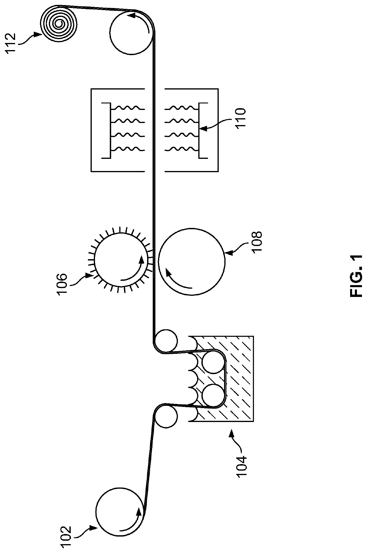
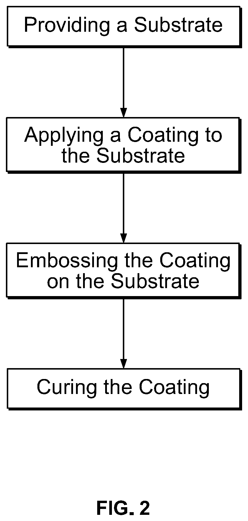
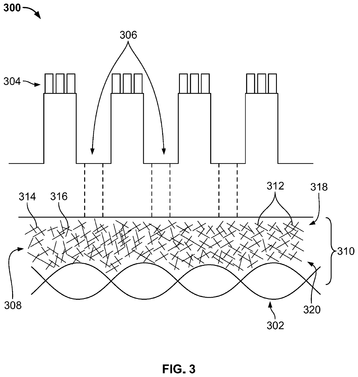

Image

  • Microstructured soft tissue graft
  • Microstructured soft tissue graft
  • Microstructured soft tissue graft

Examples


example 1

A Microstructured Surface

[0088]Referring to FIG. 5, a microstructured surface 500 is disclosed which may include a substrate 502. The substrate 502 may include a first sinusoidal microstructure 504, second pillar microstructure 506 disposed on the sinusoidal microstructure, and third fluted microstructure 508 disposed on the second pillar microstructure. Each of the three different microstructures are arranged hierarchically. The diameter, pitch, and height for each of the microstructures may be defined as follows. The first sinusoidal microstructure dimensions are 1.1× to 10× the dimensions of the second pillar microstructure dimensions. The second pillar microstructure dimensions may be 1.1× to 10× the dimensions of the third fluted microstructure dimensions. The second pillar microstructures can have any elliptical or polygonal cross section.

example 2

Mesh Coating a Microstructure Prepolymer

[0089]In certain embodiments, microstructures can be formed in polymers which crosslink to a fixed shape or are swellable. Swelling microstructures may have the added advantage of actively engaging a target surface, such as tissue, as the microstructure swells.

[0090]Poloxamer and Polylactic Acid Based Hydrogel

[0091]Pluronic 31R1 (molecular weight 3250) (BASF, Mt. Olive, N.J.) was dried under vacuum at 85° C. for 12 hours in a spherical flask. The final water content obtained was below 300 ppm. One equivalent of Pluronic 31R1 was added to ⅕ equivalent (1)-Lactide and 0.18 grams catalyst (stannous 2-ethyl hexanoate) (0.43%). The reaction was carried out in a sealed flask, under a dry nitrogen saturated atmosphere, for two and half hours at 145° C.

[0092]To the above synthesis is added 2 equivalents of toluene diisocyanate and reacted at 60° C. for 8 hours. To this result is added ½ equivalent of a biofunctional molecule, for example a boswellia e...

example 3

Polyethylene Glycol and Polylactic Acid Base Hydrogel

[0095]Polyethylene glycol (“PEG”) (molecular weight 3000) was dried in vacuo overnight at 85° C. Thereafter, the PEG was cooled to room temperature and the product capped with dry nitrogen. One equivalent of PEG was added to ⅕ equivalent (1)-Lactide and 0.18 grams catalyst (stannous 2-ethyl hexanoate). The mixture of PEG and lactide was placed in an oil bath under flowing nitrogen at 140° C. and mixed for 3 hours.

[0096]To the above synthesis is added 2 equivalents of toluene diisocyanate and reacted at 60° C. for 8 hours. To this result is added ½ equivalent of a biofunctional molecule, for example a boswellia extract and reacted at 75° C. for 8 hours.

[0097]A hydrogel of desired viscosity is formed by adding appropriate amounts of water. For example, for high a viscosity gel, 1 g water may be added. For a low viscosity gel, 100 g of water may be added.


PUM

PropertyMeasurementUnit
Lengthaaaaaaaaaa
Fractionaaaaaaaaaa
Diameteraaaaaaaaaa

Abstract

The present disclosure comprises micropatterned fabric, meshes, textiles, and implantable devices which may include having one substrate including a mesh, a second substrate having a microstructured surface, and a fibrous layer disposed therebetween. The fibrous layer comprises a plurality of randomly oriented fibers. The devices having the microstructured surface may include a plurality of first level microfeatures and a plurality of second level microfeatures wherein the plurality of second level microfeatures are disposed hierarchically the first level microfeatures. Also disclosed are methods for making such micropatterned fabric, meshes, textiles, and implantable devices

Description

CROSS-REFERENCES TO RELATED APPLICATIONS[0001]This application claims benefit of the following patent application(s) which is / are hereby incorporated by reference: U.S. Provisional Application No. 63 / 061,166 filed on Aug. 4, 2020[0002]A portion of the disclosure of this patent document contains material that is subject to copyright protection. The copyright owner has no objection to the reproduction of the patent document or the patent disclosure, as it appears in the U.S. Patent and Trademark Office patent file or records, but otherwise reserves all copyright rights whatsoever.STATEMENT REGARDING FEDERALLY SPONSORED RESEARCH OR DEVELOPMENT[0003]Not ApplicableREFERENCE TO SEQUENCE LISTING OR COMPUTER PROGRAM LISTING APPENDIX[0004]Not ApplicableBACKGROUND[0005]The present invention relates generally to micropatterned fabric, meshes, textiles, and the like. More particularly, this disclosure pertains to devices of, and methods for creating, a substrate having disposed thereon a microp...

Claims


Application Information

Patent Timeline
IPC IPC(8): A61F2/00D04H1/728D04H1/74
CPCA61F2/0063D04H1/728D04H1/74D10B2509/00A61F2210/0004A61F2240/001D10B2321/022A61F2002/0068A61F2002/0081A61F2/0077A61L2400/18A61L2430/34A61L31/10A61L31/129A61L31/148
Inventor MILBOCKER, MICHAELBLUECHER, LUKAS
Owner BVW HLDG
Learn More