Particulate composite materials

Active Publication Date: 2022-02-24
GRP 14 TECH INC
View PDF0 Cites 14 Cited by
  • Summary
  • Abstract
  • Description
  • Claims
  • Application Information

AI Technical Summary

Benefits of technology

[0010]Composites comprising Group14 elements such as silicon and carbon, are disclosed, wherein said composites have novel properties that overcome the challenges for providing amorphous nano-sized silicon entrained within porous carbon. Said silicon-carbon composites may be produced via chemical vapor infiltration to impregnate amorphous, nano-sized silicon within the pores of a porous scaffold. Suitable porous scaffolds include, but are not limited to, porous carbon scaffolds, for example carbon having a pore volume comprising micropores (less than 2 nm), mesopores (2 to 50 nm), and/or macropores (greater than 50 nm). Suitable precursors for the carbon scaffold include, but are n

Problems solved by technology

For example, current lead acid automobile batteries are not adequate for next generation all-electric and hybrid electric vehicles due to irreversible, stable sulfate formations during discharge.
However, silicon exhibits large volume change during cycling, in turn leading to electrode deterioration and solid-electrolyte interphase (SEI) instability.
Thus far, techniques for creating nano-scale silicon involve high-temperature reduction of silicon oxide, extensive particle diminution, multi-step toxic etching, and/or other cost prohibitive processes.
Likewise, common matrix approaches involve expensive materials such as graphene or nano-graphite, and/or require complex processi

Method used


Image

  • Particulate composite materials
  • Particulate composite materials
  • Particulate composite materials

Examples


example 1

[0128] Production of silicon-carbon composite material by CVI. The properties of the carbon scaffold (Carbon Scaffold 1) employed for producing the silicon-carbon composite is presented in Table 3. Employing Carbon Scaffold 1, the silicon-carbon composite (Silicon-Carbon Composite 1) was produced by CVI as follows. A mass of 0.2 grams of amorphous porous carbon was placed into a 2 in.×2 in. ceramic crucible then positioned in the center of a horizontal tube furnace. The furnace was sealed and continuously purged with nitrogen gas at 500 cubic centimeters per minute (ccm). The furnace temperature was increased at 20° C. / min to 450° C. peak temperature where it was allowed to equilibrate for 30 minutes. At this point, the nitrogen gas is shutoff and then silane and hydrogen gas are introduced at flow rates of 50 ccm and 450 ccm, respectively for a total dwell time of 30 minutes. After the dwell period, silane and hydrogen were shutoff and nitrogen was again introduced to the furnace t...

example 2

[0129] Analysis of various silicon-composite materials. A variety of carbon scaffold materials were employed, and the carbon scaffold materials were characterized by nitrogen sorption gas analysis to determine specific surface area, total pore volume, and fraction of pore volume comprising micropores, mesopores, and macropores. The characterization data for the carbon scaffold materials is presented in Table 4, namely the data for carbon scaffold surface area, pore volume, and pore volume distribution (% micropores, % mesopores, and % macropores), all as determined by nitrogen sorption analysis.

TABLE 4Properites of various carbon scaffold materials.CarbonSurfacePore%%%ScaffoldAreaVolumeMicro-Meso-Macro-#(m2 / g)(cm3 / g)poresporespores117100.76293.16.80.1217440.7297.22.70.1315810.83269.130.90.1417100.81780.119.90518350.982.217.80614751.0652.447.6074530.53.991.15.187872.284059.140.9917130.769190

[0130]The carbons scaffold sample as described in Table 4 were employed to produce a variety o...

example 3

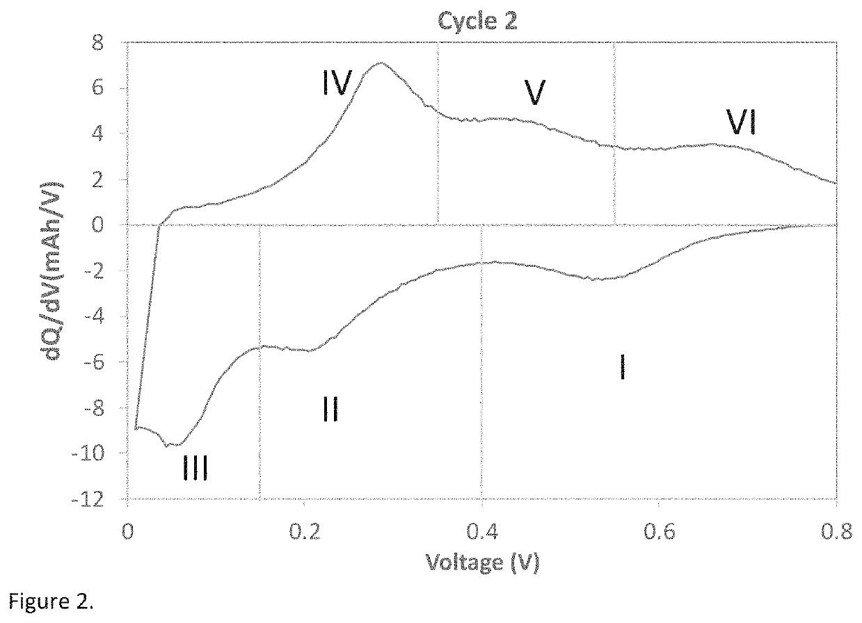
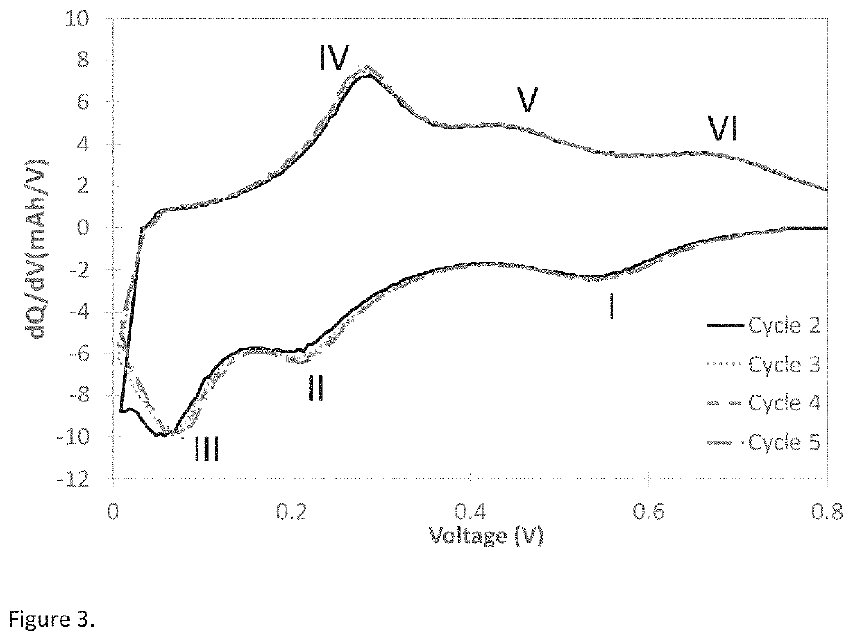
[0137] dV / dQ for various silicon-composite materials. Differential capacity curve (dQ / dV vs Voltage) is often used as a non-destructive tool to understand the phase transition as a function of voltage in lithium battery electrodes (M. N. Obrovac et al. Structural Changes in Silicon Anodes during Lithium Insertion / Extraction, Electrochemical and Solid-State Letters, 7 (5) A93-A96 (2004); Ogata, K. et al. Revealing lithium-silicide phase transformations in nano-structured silicon-based lithium ion batteries via in situ NMR spectroscopy. Nat. Commun. 5:3217). Differential capacity plots presented here is calculated from the data obtained using galvanostatic cycling at 0.1C rate between 5 mV to 0.8V in a half-cell coin cell at 25° C. Typical differential capacity curve for a silicon-based material in a half-cell vs lithium can be found in many literature references (Loveridge, M. J. et al. Towards High Capacity Li-Ion Batteries Based on Silicon-Graphene Composite Anodes and Sub-micron V...


PUM

PropertyMeasurementUnit
Temperatureaaaaaaaaaa

Abstract

Particulate composite materials and devices comprising the same are provided.

Description

BACKGROUNDTechnical Field[0001]Embodiments of the present invention generally relate to particulate composite materials and devices comprising the same.Description of the Related Art[0002]CVI is a process wherein a gaseous substrate reacts within a porous scaffold material. This approach can be employed to produce composite materials, for instance silicon-carbon composites, wherein a silicon-containing gas decomposes at elevated temperature within a porous carbon scaffold. While this approach can be employed to manufacture a variety of composite materials, there is particular interest in silicon-carbon (Si—C) composite materials. Such Si—C composite materials have utility, for example as energy storage materials, for example as an anode material within a lithium ion battery (LIB). LIBs have potential to replace devices currently used in any number of applications. For example, current lead acid automobile batteries are not adequate for next generation all-electric and hybrid electri...

Claims


Application Information

Patent Timeline
IPC IPC(8): C01B33/035C01B32/354
CPCC01B33/035C01B32/354C01P2006/14B82Y30/00C01P2002/02C01P2004/61C01P2006/40C01P2006/12C01B32/05C01B33/027C01P2002/30C01P2004/60C04B38/0054H01M4/13H01M4/139H01M4/364F05D2300/603F01D25/005B82Y40/00H01M10/0525H01M4/386H01M4/587C04B2111/00853Y02E60/10C04B38/0032C04B35/52C04B38/0074C04B41/5096C04B35/565
Inventor COSTANTINO, HENRY R.DHANABALAN, ABIRAMISAKSHAUG, AVERY J.
Owner GRP 14 TECH INC
Why Eureka
Try Eureka