Delay process to provide timed chemistry to lateral-flow immunoassays

a technology of immunoassay and lateral flow, which is applied in the direction of instruments, color/spectral properties measurements, material analysis, etc., can solve the problems of increasing the size of the nanoparticle label, limited sensitivity of lfias, and insufficient sensitivity for some applications, so as to achieve simple use and improve sensitivity

Pending Publication Date: 2022-02-24
THE UNITED STATES OF AMERICA AS REPRESENTED BY THE SECRETARY OF THE NAVY
View PDF5 Cites 0 Cited by
  • Summary
  • Abstract
  • Description
  • Claims
  • Application Information

AI Technical Summary

Benefits of technology

[0010]The present invention provides a system and method to provide delayed release of chemical reagents in LFIAs. A chemistry release fiber comprising a permeable membrane and a chemical release agent

Problems solved by technology

The sensitivity of LFIAs is limited by the optical density of the gold label and this sensitivity is inadequate for some applications.
One can increase the size of the nanoparticle label and thereby increase the optical density at the expense of performance in the LFIA, but even that has its limits as very large particles will not migrate up the strip under the capillary action of the mobile phase.
However, this chemical enhancement comes at the cost of increased complexity and user intervention in the LFIA system to delay the chemistry until

Method used


Image

  • Delay process to provide timed chemistry to lateral-flow immunoassays
  • Delay process to provide timed chemistry to lateral-flow immunoassays
  • Delay process to provide timed chemistry to lateral-flow immunoassays

Examples


example 1

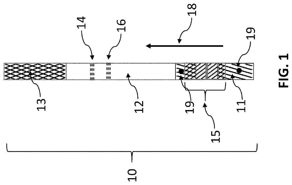
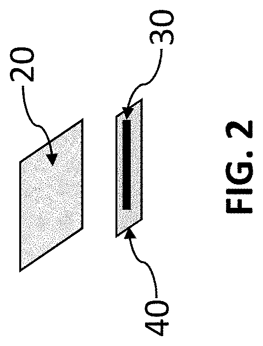
[0033]Two fibers are used as fiber 30. One is impregnated with a hydrogen peroxide precursor that releases hydrogen peroxide upon exposure to water. The second fiber (not shown in FIG. 1) is impregnated with two dye precursors that are for precipitating dye in the presence of a catalyst. This example uses catalyst dye chemistry impregnated on the second fiber as outlined by Kidwell (Kidwell, “Catalytic Particles for Increased Sensitivity in Lateral Flow Immunoassays,” United States Patent Application 20180052153, Feb. 22, 2018 and Kidwell et al., “Catalytic Particles For Signal Enhancement For Lateral Flow Immunoassays,” United States Patent Application 20190339265, Nov. 7, 2019).

[0034]The second fiber was prepared by soaking cotton twine (average 225 μm diameter) in a solution of 40 mg / mL 4-Hydroxy-1-naphthalenesulfonic acid sodium salt (CAS #6099-57-6), 30 mg / mL N,N-Diethyl-p-phenylenediamine (CAS #6283-63-2), and 20 mg / mL citric acid (CAS #77-92-9) in equal parts ethanol and wate...

example 2

[0039]A method to easily visualize the working of the chemical release fiber construct 15 is to use precursors that form a dye upon reaction with a catalyst. It is especially useful to use precursors for the reaction of hydrogen peroxide in the presence of a palladium catalyst. Fiber 30 was constructed as in Example 1. Five different types of chemical release fiber constructs 15, done in triplicate, were constructed with different membranes 40. The constructs were placed on the nitrocellulose strip 12. The average time to just start the development of the line at the catalyst are shown in Table 1 for various chemical release fiber constructs 15. As can be seen in Table 1, the time can be varied over a long period though simply changing the membrane or the number of layers.

TABLE 1Time to just observe the start of dye formation. The running solution was 1% hydrogen peroxide in 100 mM sodium carbonate buffer. The catalyst was sprayed at approximately 30 ng / line.Construct of Time to Sta...

example 3

[0040]An additional method to easily visualize the working of the chemical release fiber construct 15 is to use colored dyes. It is especially useful to use anionic dyes as they have less affinity for the components of the chemical release fiber construct 15 and the lateral-flow immunoassay construct 10. pH sensitive dyes such as bromophenol blue are preferred as they change color form yellow to blue on a pH shift. The dye is loaded in fiber 30 in acid media and dried, the fiber will be yellow in color. If the test solution were basic, the rate of hydration of the fiber can be readily measured by the color change. Likewise, the release of the now blue dye into the flowing stream on nitrocellulose 12 can be easily visualized.

[0041]FIG. 7A is a photograph of a chemical release fiber construct 15 directly on nitrocellulose 12 after the interior fiber 20 has just been hydrated. FIG. 7B is a photograph of a chemical release fiber construct 15 directly on nitrocellulose 12 during the rele...


PUM


Abstract

The present invention provides for a release system for delaying application of chemical reagents in a lateral-flow immunoassay. A chemistry release fiber comprising a permeable membrane and a chemical release agent is used to delay chemical reagent delivery to the indicator of a lateral-flow immunoassay. Also disclosed is the related method of delaying application of chemical reagents in a lateral-flow immunoassay.

Description

PRIORITY CLAIM[0001]The present application claims the benefit of U.S. Provisional Application No. 63 / 068,752, filed on Aug. 21, 2020 by David A. Kidwell, entitled “DELAY PROCESS TO PROVIDE TIMED CHEMISTRY TO LATERAL-FLOW IMMUNOASSAYS,” the entire contents of which is incorporated herein by reference.BACKGROUND OF THE INVENTIONField of the Invention[0002]The present invention relates to providing a delayed release of chemical reagents in lateral-flow immunoassays unencumbered by operator intervention.Description of the Prior Art[0003]Lateral-flow immunoassays (LFIAs) are common point-of-care (POC) tests for a wide variety of diseases and compounds. The best known are home pregnancy tests. LFIAs have the advantages of rapid results, no required instrumentation, and self-timed due to the capillary flow of the analytes on the strip. LFIAs typically use colored particles as the visual label—most often colloidal gold particles or colored latex that are localized at a line due to a biolog...

Claims


Application Information

Patent Timeline
IPC IPC(8): G01N33/543G01N33/52G01N21/78G01N21/29
CPCG01N33/54388G01N33/525G01N2201/04G01N21/29G01N21/78
Inventor KIDWELL, DAVID A.
Owner THE UNITED STATES OF AMERICA AS REPRESENTED BY THE SECRETARY OF THE NAVY
Why Eureka
Try Eureka