Check patentability & draft patents in minutes with Patsnap Eureka AI!

Two dimensional transducer arrays for ultrasound imaging

a transducer array and ultrasound technology, applied in the field of ultrasound imaging two-dimensional transducer arrays, can solve the problems of reducing the transmit voltage, using unipolar pulsers, and compromising array performance, so as to achieve additional redundancy and improve uniformity

Pending Publication Date: 2022-03-10
UNIV OF SOUTHERN CALIFORNIA
View PDF6 Cites 0 Cited by
  • Summary
  • Abstract
  • Description
  • Claims
  • Application Information

AI Technical Summary

Benefits of technology

This patent describes an ultrasound imaging system with several technical features. Firstly, the system uses an inverse filter to minimize noise in the image. Secondly, apodization is applied to reduce the effects of a high sidelove level and clutter in the point spread function. Lastly, the system employs a matrix of transducer elements arranged in rows and columns, with additional redundancy in each row or column to improve image quality. These technical features can enhance the accuracy and reliability of ultrasound imaging for medical purposes.

Problems solved by technology

This may lead to compromises in array performance such as lowering transmit voltages and using unipolar pulsers.
It may also frequently require relaxing the noise performance of receive amplifiers to greatly reduce the dissipated current in the probe handle.
The main challenge with this architecture is the fact that the transmit and receive circuitry for a particular element may have to sit immediately behind the transducer and may have therefore to occupy a limited area dictated by the 2D array element pitch.
The problem may especially be acute when both low voltage (LV) and high voltage (HV) devices are used because HV devices may typically be 10× larger than equivalent functionality LV devices due to the requirements for voltage standoff for isolation.
The compromise may require the HV circuitry to be reduced in functionality and / or transmit voltage, while the LV circuitry may require sacrifice in noise performance due to the limitation on the size of the input pair which may determine the thermal and 1 / f noise of the receive circuit.
In addition, HV fabrication processes typically lag LV in process node integration which may mean that the digital circuitry will not be optimized and will also consume significant area behind the elements, further compromising performance.
Substrate crosstalk between transmit and receive circuits may also present a challenge with highly integrated systems.
With 2D imaging, it is not feasible to fine the same image plane on a consistent basis over time as is needed for serial monitoring.
3D ultrasound systems may have different levels of complexity ranging from the use of spatial locators integrated with 2D imaging systems to fully-sampled 2D arrays with true 3D beamforming and steering.
A disadvantage of such systems may be the increased sidelobe levels and clutter in the image.
Developing fully-sampled 2D arrays having several thousands of elements may technologically be difficult and expensive.
ASICs may also have several disadvantages including a noise-power tradeoff, heat dissipation, and sacrifices in hardware performance.

Method used


Image

  • Two dimensional transducer arrays for ultrasound imaging
  • Two dimensional transducer arrays for ultrasound imaging
  • Two dimensional transducer arrays for ultrasound imaging

Examples


example 1

ray Layout

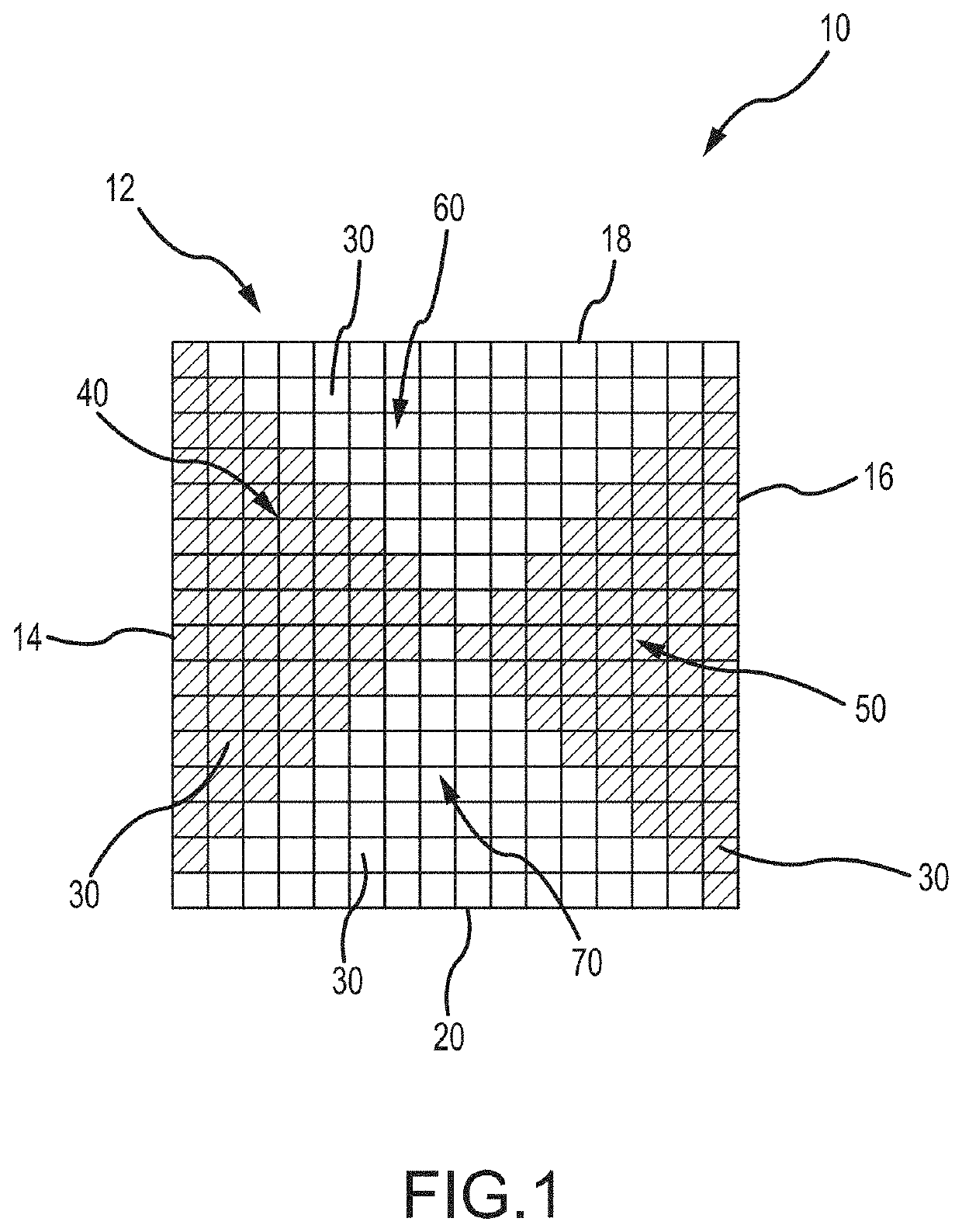
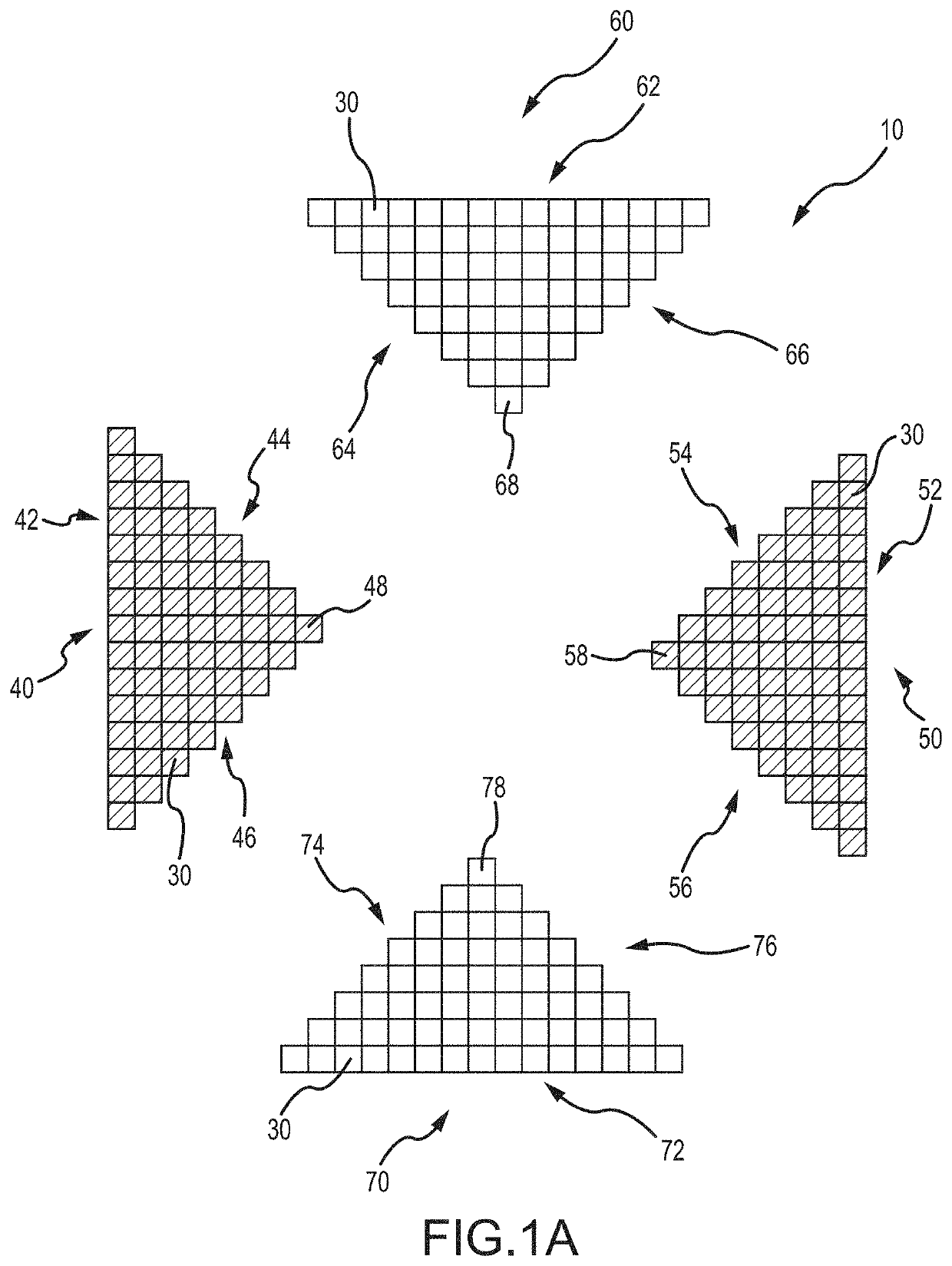
[0236]For illustrative purposes, a bowtie array layout of a 16×162D array 10 is shown in FIG. 1. By way of initial summary, the array 10 may be characterized as consisting of four triangles whose apexes meet at least substantially at the center of the array 10. Certain groups of elements are used in transmit only and other groups of elements are used in receive only. These groups of elements are interfaced to separate transmit and receive interface electronics which are implemented using both high voltage and low voltage Application Specific Integrated Circuit (ASIC) fabrication processes. It is assumed that separate transmit and receive ASICs are capable of micro-beamforming where clusters of transmit only elements or receive only elements are bundled to one system channel. At the element level, fine delays in transmit and receive combined with coarser delays at the system level provide beamforming equivalent to conventional delay-and-sum beamforming.

[0237]The ultrasound ...

example 2

ystem Response in k-Space

[0244]The frequency domain or k-space response of an ultrasound imaging system, ATR, may be estimated by the convolution of spatially scaled and reversed representations of the transmit and receive aperture weighting functions indicated by AT and AR respectively:

ATR(fx,fy)=AT(fx,fy)*AR(fx,fy)  Equation (1)

[0245]In Equation 1, fx and fy are the azimuthal and elevational spatial frequencies respectively, and the asterisk indicates two-dimensional (2-D) convolution. In one example, this may give the results shown in FIG. 2 for the fully sampled array in the top row and the bowtie array in the bottom row. The full 2-D k-space response is shown in the left column, and the azimuthal k-space response of each array is shown in the right column. The elevational k-space response is identical to the azimuthal due to symmetry. As shown, the bowtie array may have the same coverage in k-space as the fully-sampled array. In all figures, the magnitudes have been normalized ...

example 3

Simulations

[0248]Simulations of a 64×643 MHz bowtie array and a 64×64 fully-sampled array were carried out using Field II Pro. Using a sound speed of 1540 m / s, the element pitch was equal to about 257 μm, or one-half wavelength. Single point targets located on axis (about 0°, about 0°, about 60 mm) and off-axis (about 40°, about 40°, about 60 mm). Beamwidths at about −6, about −20, and about −40 dB were measured. Simulations involving multiple point targets was also performed. Five point targets were evenly spaced every about 10 degrees from about −20° to about +20°. Additionally, five point targets were spaced evenly in the axial direction from about 40 mm to about 80 mm, giving a total of about 125 point targets. A speckle target with an about 8 mm diameter spherical cyst located at about 60 mm depth was also simulated.

[0249]The phantom size was about 50 mm×about 50 mm×about 30 mm. 12 scatterers per resolution volume were used. The transmit and receive focus is set to an about 60 ...


PUM


Abstract

Two-dimensional transducers arrays for ultrasound imaging is disclosed. The two-dimensional arrays are suitable for formation of two-dimensional (2D) and / or three-dimensional (3D) ultrasound images. The two-dimensional arrays are suitable for real-time 2D and / or 3D ultrasound imaging. The bowtie transducer arrays and the rectangular transducer arrays are suitable for real-time 2D and / or 3D ultrasound imaging.

Description

CROSS-REFERENCE TO RELATED APPLICATIONS[0001]This patent application is a non-provisional patent application of, and claims the benefit of, co-pending U.S. Provisional Patent Application No. 63 / 074,931, that was filed on Sep. 4, 2020, and the entire disclosure of which is hereby incorporated by reference herein.BACKGROUND OF THE INVENTIONField of the Invention[0002]This invention relates to two dimensional transducers arrays for ultrasound imaging. This invention also relates to two dimensional arrays suitable for formation of two dimensional (2D) and / or three dimensional (3D) ultrasound images. This invention further relates to two dimensional arrays suitable for real-time 2D and / or 3D ultrasound imaging. This invention further relates to bowtie transducer arrays and rectangular transducer arrays suitable for real-time 2D and / or 3D ultrasound imaging.Description of the Related Art[0003]Ultrasound probes utilizing 2D array transducers enable reliable real-time 3D imaging. Since thei...

Claims


Application Information

Patent Timeline
Patent Type & Authority Applications(United States)
IPC IPC(8): A61B8/00A61B8/08
CPCA61B8/4494A61B8/483A61B8/4488A61B8/5207G01S15/8925G01S15/8993G01S7/52026G01S15/8913G01S15/8961G01S15/8927
Inventor YEN, JESSE TONG-PINWODNICKI, ROBERT G.
Owner UNIV OF SOUTHERN CALIFORNIA
Features
  • R&D
  • Intellectual Property
  • Life Sciences
  • Materials
  • Tech Scout
  • Unparalleled Data Quality
  • Higher Quality Content
  • 60% Fewer Hallucinations
Learn More