Composite thermal barrier materials

a thermal barrier and composite technology, applied in the field of composite thermal barrier materials, can solve the problems of affecting the safety of people, and thicker thermal barrier films, and achieve the effects of ensuring the safety of the battery pack

Pending Publication Date: 2022-05-26
HEFEI GUOXUAN HIGH TECH POWER ENERGY
View PDF0 Cites 0 Cited by
  • Summary
  • Abstract
  • Description
  • Claims
  • Application Information

AI Technical Summary

Benefits of technology

[0022]According to the present invention, the composite thermal barrier material includes a thermal insulating aerogel material as the inner layer and a robust resin layer containing three functional fillers as the outer layer, thus a sufficient mechanical support can be achieved while having an excellent thermal insulation property. Thus, the composite thermal barrier material according to the present invention can solve the above technical problems in the prior art and help to stop the thermal propagation when one cell has thermal runaway. In addition, the battery pack comprising the composite thermal barrier material can protect the battery pack from thermal damage due to thermal runaway of one cell and ensure a safe design of the battery pack.

Problems solved by technology

However, the safety is a problem due to the high composition of chemical active substance.
When a cell suffers from high temperature or overcharging or internal short, it may get into thermal runaway situation, as the result, the battery pack may be exposed to fire or explosion because of thermal propagation, thereby seriously endangering personal safety.
However, it is commonly recognized in the art that such a thermal barrier film is thicker and has a relatively poor effect.
However, the aerogel, per se, has a low structural strength and high fragility, thus has poor effect when individually used as a thermal barrier sheet in an electronic device.
The two flame-retardant layers are aluminum-foil or glass-fiber flameproof textile, thus may have poor adhesion to the aerogel material.

Method used


Image

  • Composite thermal barrier materials
  • Composite thermal barrier materials

Examples


example 1

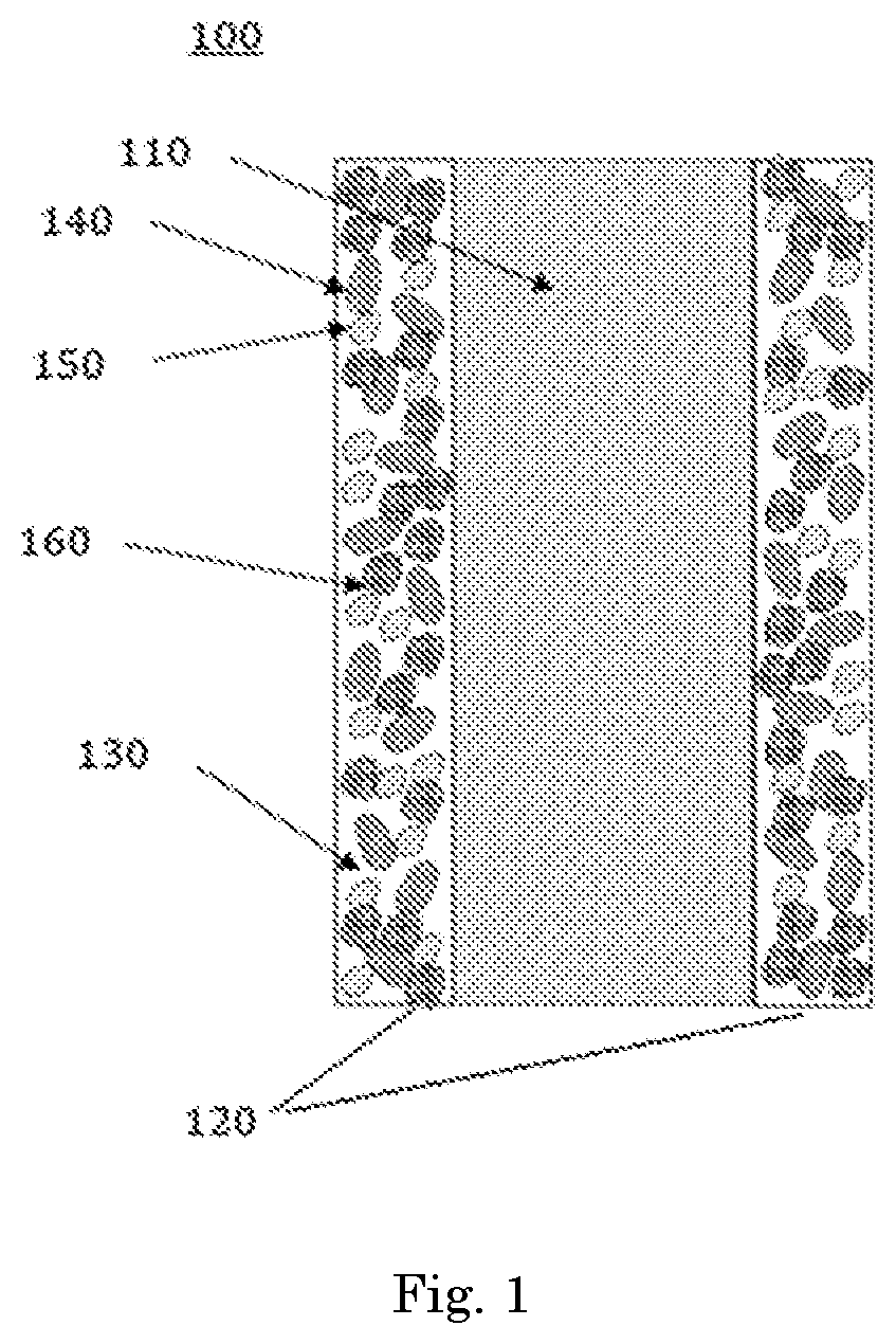
[0095]Preparation of a SiO2 / TiO2 Aerogel

[0096]A SiO2 / TiO2 aerogel is prepared by the steps (1) to (4) as follows:

[0097](1). First, 4 g Na4SiO4 (Sigma Aldrich) and 3 g Na2Ti3O7 (Sigma Aldrich) having a nano size were weighed and added to 100 ml of distilled water, stirred well to prepare a stable aqueous solution of Na4SiO4 and Na2Ti3O7.

[0098](2). An alkaline solution (1 M KOH, Sigma Aldrich) was slowly added into the stable solution to adjust pH of the stable solution to 3.5 to form a SiO2 / TiO2 sol.

[0099](3). The obtained SiO2 / TiO2 sol was aged in water for 10 h to form a gel.

[0100](4). The aged gel was incubated in a supercritical CO2 medium at a supercritical temperature of 50° C. for 2 h to form a SiO2 / TiO2 aerogel.

[0101]By the above steps (1) to (4), an aerogel containing 72 wt % of SiO2 / TiO2 was obtained. In addition, 25 wt % of SiC (opacifier, Sigma Aldrich, 378097) and 3 wt % of glass fiber (binder, Asashi Kasei, PA66) was also added in step (1). The obtained SiO2 / TiO2 aeroge...

example 2

[0106]The composite thermal barrier film was prepared by the same process as that described in Example 1, except that the aerogel is prepared to have a thickness of 1 mm.

[0107]The composite thermal barrier film was placed on a hot plate, with one side thereof contacted the hot plate, and heated to 600° C. for 300s. The temperature of the other side of the thermal barrier film was recorded. The result is listed in the below table 1.

example 3

[0108]The composite thermal barrier film was prepared by the same process as that described in Example 1, except that the aerogel is prepared to have a thickness of 2 mm.

[0109]The composite thermal barrier film was placed on a hot plate, with one side thereof contacted the hot plate, and heated to 600° C. for 300s. The temperature of the other side of the thermal barrier film was recorded. The result is listed in the below table 1.


PUM

PropertyMeasurementUnit
thicknessaaaaaaaaaa
thicknessaaaaaaaaaa
thicknessaaaaaaaaaa

Abstract

A composite thermal barrier material (100) has a sandwich structure, and comprises an inner layer (110) consisting of an aerogel material which has ultra-low thermal conductivity; and two flame retardant layers (120) which comprising a flame retardant resin matrix (130), wherein the inner layer (110) is sandwiched by the two flame retardant layers (120), and the flame retardant layer (120) also contains an expandable graphite (140), a high temperature decomposable material (150) and a phase change material (160) as functional fillers dispersed in the flame retardant resin matrix (130). The composite thermal barrier material (100) has excellent thermal insulation property, and may stop the thermal propagation when one cell has thermal runaway.

Description

TECHNICAL FILED[0001]The present invention relates to thermal barrier materials that used in battery module or pack to stop the thermal propagation.BACKGROUND ART[0002]Over the last two decades, lithium ion batteries have become highly desired power source for new energy vehicle. The current commercially available lithium ion batteries with a graphite anode and layer-structure LIMO (M=Ni, Co, Mn binary or ternary system) cathode have a gravimetric energy more than 250 Wh / kg at the cell level. The industry is continuously pursing for even higher energy density (>300 Wh / kg).[0003]Comparing with lithium ion phosphate batteries with relative lower energy density (160-180 Wh / kg), NCM or NCA based batteries have great advantages in terms of high energy density. However, the safety is a problem due to the high composition of chemical active substance. When a cell suffers from high temperature or overcharging or internal short, it may get into thermal runaway situation, as the result, th...

Claims


Application Information

Patent Timeline
Patent Type & Authority Applications(United States)
IPC IPC(8): H01M50/431H01M50/457H01M50/454H01M10/052H01M10/658H01M50/414
CPCH01M50/431H01M50/457H01M50/414H01M10/052H01M10/658H01M50/454H01M10/0525H01M50/20Y02E60/10C08J2381/04C08J2369/00C08J7/04
Inventor ZHANG, YACHENG, QIANCAI, STEVEN
Owner HEFEI GUOXUAN HIGH TECH POWER ENERGY
Why Eureka
Try Eureka