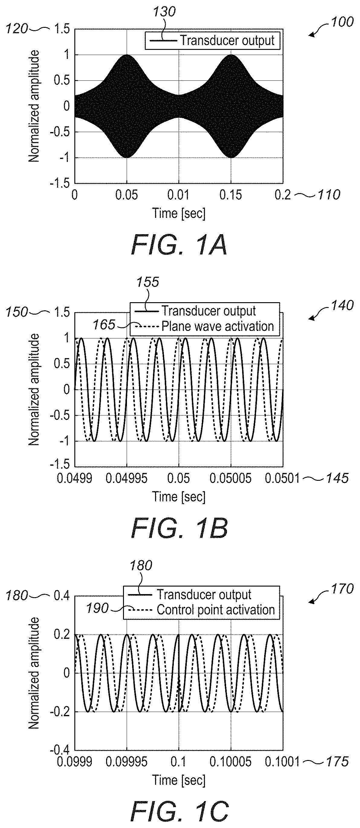
Furthermore, tracking a user's hand while also providing reasonable haptic sensations to the same hand using an acoustic field and without interruption adds to the challenge; conventional
ranging techniques are deemed unsuitable as they would require significant interruption to the haptic sensations.
Given that the
system is providing haptic sensations using an acoustic field, then using technologies other than acoustic excitation and reception for the location and tracking of the user's hand in the volume adds to the cost and complexity of the final implementation.
This fundamentally limits the maximum update rate of the
system to be the ratio of the distance between emitter and reflector to the relatively
slow speed of sound.
A further restriction is that while generating haptic sensations, it is undesirable to interrupt the
haptic sensation generation in order to transmit and receive a
ranging pulse as this would likely interfere with or diminish the haptic sensations.
Once again, this is based on a transient
ranging technique and is thus significantly limited in the maximum update rate due to the time taken for sound to complete the journey.
It is important in such transient techniques to allow separation in time between adjacent ranging pulses to complete the journey, otherwise the
receiver is unable to differentiate between them and therefore cannot determine the location of the reflector unambiguously.
Using subsonic frequencies means that the sensitivity of the system would be low, requiring disproportionate cost to implement with sufficiently
high fidelity as to resolve small changes in phase of a subsonic
wavelength for reasonable changes in physical displacement of a reflector.
In
real systems, the natural
noise in the implementation is likely to be a significant challenge to attain the fidelity, or
signal-to-
noise ratio, required to estimate small changes in distance accurately.
Using ultrasonic frequencies can be equally challenging in different areas.
For example, the system becomes too sensitive, delivering a
high rate of change of
phase difference for small changes in physical displacement.
Given this, it becomes difficult, if not impossible, to locate a reflector that is more than half a
wavelength away from
transmitter and
receiver.
Furthermore, if a reflector moves more than half a
wavelength between adjacent measurements then the system cannot determine the location without
ambiguity and without significant cost and complexity of implementation.
The practical utility of comparing the phase of the received wave to that of the wave being transmitted diminishes rapidly with increasing
acoustic wave frequency and thus the systems is ultimately less reliable and less accurate.
Therefore, the location and tracking proceeds while also providing uninterrupted haptic sensations from the same
transducer array.
This sudden change in the output amplitude, which is usually in the form of a sharp attenuation, creates substantial audible
noise from the array of transmitting transducers.
This sudden change in the output amplitude, which is usually in the form of a sharp attenuation, creates substantial audible noise from the array of transmitting transducers.
A modulation at a single haptic frequency does not necessarily provide the most effective haptics for a
control point.
Interpolating between a zero state and a state corresponding to a multiple valid control points that are amplitude modulated is inefficient, as for half of the time the device is moving towards the zero state in which nothing is output.
This means that in situations in which the system is resource constrained and three points are presented as equal, two of the control points are noticeably weaker, leading to a haptic effect that is not as effective.
This causes the amplitude at
control point to slightly blur and not being optimized.
Further, in a naïve experimental set up, transducers may not send and receive at the same time.
The main problem with this approach is that introducing a phase singularity into each
transducer causes it to work against the other transducers contributing to the focusing or control region behavior that has been prescribed to create the haptic effects.
The other issue with the system so far described is that it is slow in time.
It should also be noted that some symbols may be missed due to
weakness.
Computation of time-of-flight happens at the
CMOS pixel array level, but material and build cost increase with respect to stereo-vision systems.
While all the aforementioned techniques achieve a full real time 3D tracking of objects with various degrees of depth accuracy and interaction areas, they often require expensive
processing to happen on external processor, requiring the shuttle of big bandwidth of data.
Also,
software complexity and build and material cost is often high.
If only a limited number of receivers in the 3D space is available, a full acoustic imaging of the target is impossible.
As introduced in section I,
camera tracking systems invite privacy concerns and are bandwidth heavy because they transport video data around.
On the square distance transformed
binary image, a stationary point detection is applied (at first, Laplacian type
edge detection was posited instead but it was ultimately not sufficiently robust).
As the warped distance measure is necessarily positive (which means that more expensive
minimum spanning tree algorithms which are compatible with negative arc weights need not be considered), a full iteration of Prim's
minimum spanning tree algorithm can be engaged when the boundary point
list fails to find an obvious choice of tree extension, resulting in a new node on the boundary node
list.
However, the initial production of a high quality
binary image is of paramount importance to the
algorithm, and so if no other effective
background subtraction algorithm can be found, the mixture of Gaussians seems to be the
gold standard approach although potentially complicated with a high level of resource usage from the standpoint of an embedded approach.
Therefore, the natural phase of such a field is unlikely to be planar and may also be changing with time.


