Optical based opacity and flow monitoring system and method of monitoring opacity and flow

Inactive Publication Date: 2000-04-18
JUNIVERSITI OF NORT KAROLINA EHT SHARLOTT
View PDF7 Cites 20 Cited by
  • Summary
  • Abstract
  • Description
  • Claims
  • Application Information

AI Technical Summary

Benefits of technology

The operation described above is repeated for each rotation of the timing wheel 46. The remote data processor 32 may display the opacity obtained each revolution, calculate and display the average opacity over a 5 minute interval, and store the 5 minute average opacity. The 5 minute average opacities are used to compute hourly averages which are also stored. Normalized cross-correlations obtained during successive revolutions of the timing wheel 46 are summed for a predetermined time period by the computer. The time period may be selected to be 5, 10 or 15 minutes. At the end of this time period, the pixel number of the maximum value stored in the array is determined and the array emptied. The pixel number of the maximum value which corresponds to the cross-correlation peak allows for determination of .DELTA.t in Eq. (5). Because the distance .DELTA.d between the two orthogonally polarized beams 58, 60 (FIG. 4) is pre-determined during the construction of the emission monitor 12, the average flow rate for the interval is easily computed using Eq. (5) by the computer in the remote data processor 32. The system and method described herein yields opacity and flow rate measurements having minimal error that could arise from the mea

Problems solved by technology

However, time-of-flight velocimetry is subject to error.
This occurrence can lead to an erroneous time-of-flight measurement when a signal from the arrival of a second particle is mistakenly identified as the departure signal of the first particle.
Current emissions monitoring systems also pose another problem in that the current systems transfer opacity and flow rate data collected by stack mounted units to a remote data processing station using electrically conducting cable.
Utilization of electrically conducting cable for data transfer results in systems with significant susceptibility to damage by lightning.
Not only can lightning destroy stack mounted units, elect

Method used


Image

  • Optical based opacity and flow monitoring system and method of monitoring opacity and flow
  • Optical based opacity and flow monitoring system and method of monitoring opacity and flow
  • Optical based opacity and flow monitoring system and method of monitoring opacity and flow

Examples


example

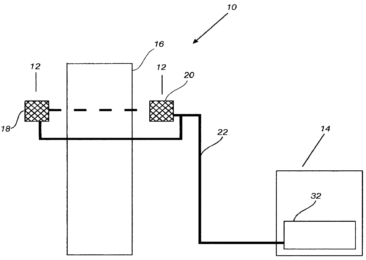
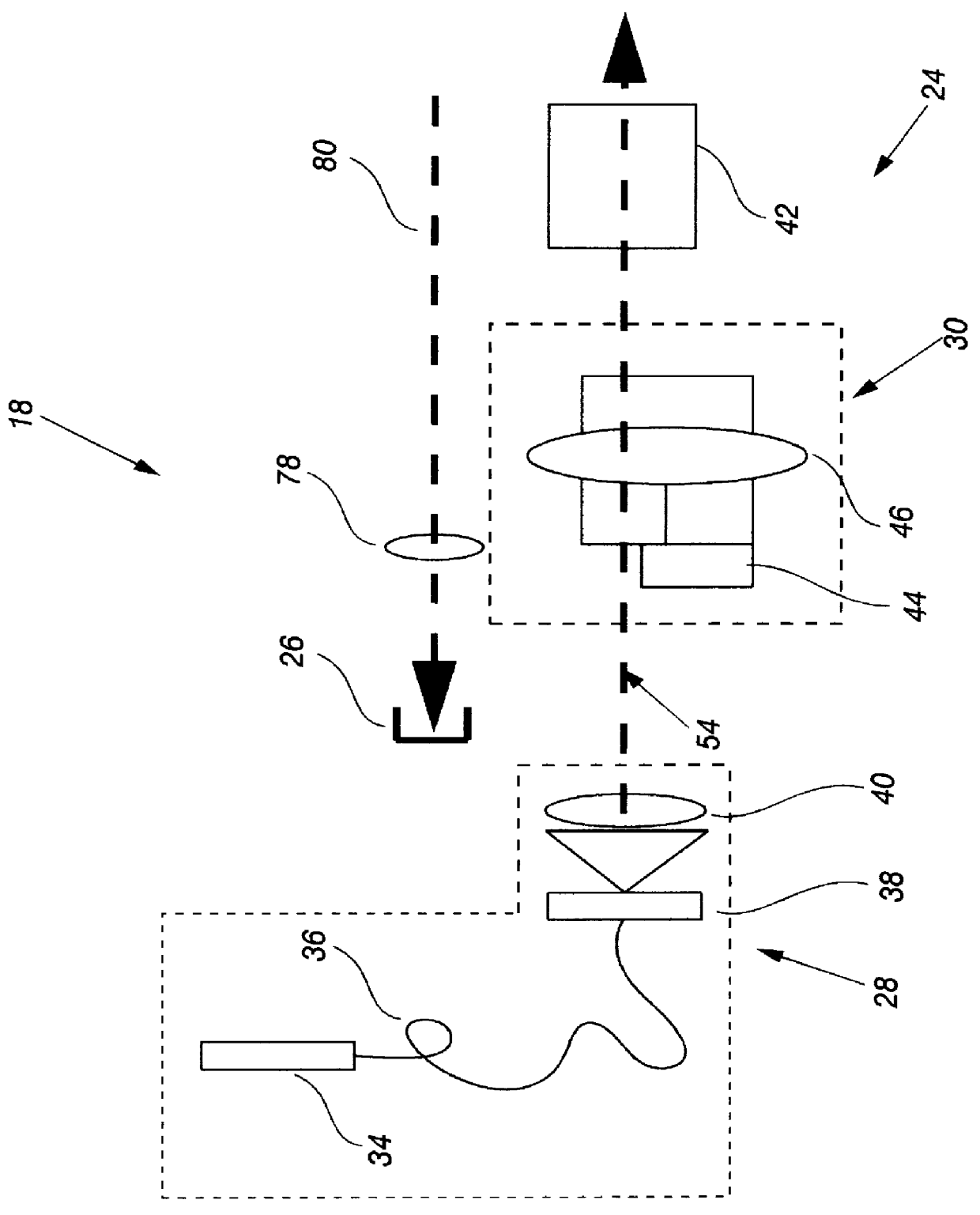
Flow rate detector signals obtained in a 6-inch line-of-sight stack having a turbulent medium are shown in FIGS. 6a and 6b. Similar signals obtained in an 18-foot line-of-sight stack operated by Duke Power Company at Allen Steam Plant in Belmont, N.C., are shown in FIGS. 7a and 7b. Flow rate data (e.g., the intensities of the light beams) is extracted from the beam after the first pass across the stack because the flow of gases in the stack involves severe turbulence. In situations involving more laminar flow, flow rate data is extracted after two, or possibly more, passes across the stack. Because of stack turbulence, the upstream and downstream signals are not identical in either FIG. 6a or FIG. 6b. Even so, a casual examination shows that the downstream signal shown in FIG. 6b is correlated in time with the upstream signal in FIG. 6b. However, due to a greater turbulence in the stack flow at Allen Steam Plant, the time displacement between the upstream and the downstream signals ...


PUM


Abstract

A pollutant emissions monitoring system and a method of measuring pollutant emissions, particularly fly ash, of gas passing through stacks of coal-fired boilers. An all optical-based emission monitor has an opacity monitor and a flow rate monitor connected to a remote data processing facility by a single fiber optic cable. A timing/calibration wheel assembly initiates measurement cycles and calibrates the opacity monitor. A first beamsplitter polarizes a collimated light beam from a light source into two collimated light beams, an upstream and a downstream beam. A second beamsplitter receives the collimated light beams, reflects a portion of the light beams to the flow rate monitor and passes the remainder of the light beams to a retro-reflector. The remote data processing facility determines the flow rate of the fly ash by measuring a plurality of pairs of upstream and downstream flow signals transmitted from the flow rate monitor, correlating each of the plurality of pairs of flow signals, normalizing the correlated flow signals and summing the normalized flow signals. The retro-reflector returns the remainder of the light beams to the opacity monitor. The remote data processing facility determines opacity by calculating optical density values based on a diffuser intensity, an offset intensity and a reflected intensity measured by the opacity monitor.

Description

The present invention relates to an optical based pollutant emissions monitoring system and method of monitoring pollutant emissions, and more particularly to an optical based opacity and flow monitoring system for pollutant emissions and method of measuring the opacity and flow rate of pollutant emissions generated as a by-product of industrial activity.Environmental Protection Agency (EPA) regulations require that industries continuously monitor the emission of atmospheric and water pollutants generated as by-products of industrial activity. Of central concern is the emission of fly ash from the stacks of coal-fired boilers. Determination of the weight of fly ash produced as by-product requires two separate measurements: (1) a measurement of the particulate density of the stack gases; and (2) a measurement of the volumetric flow rate of the gases passing through the stack. As defined herein, "opacity" is the fraction of incident light which is lost in transmission through an optic...

Claims


Application Information

Patent Timeline
IPC IPC(8): G01N21/47G01N21/53
CPCG01N21/534
Inventor FARAHI, FARAMARZMAYES, TERRILL W.
Owner JUNIVERSITI OF NORT KAROLINA EHT SHARLOTT
Why Eureka
Try Eureka