Manufacture of test strips

a technology of test strips and manufacturing methods, applied in the direction of biomass after-treatment, analysis using chemical indicators, instruments, etc., can solve the problems of unfavorable reagent stability, inability to provide casings, and inability to completely fix previously deposited reagents to the carrier, etc., to achieve the effect of promoting reagent stability

Inactive Publication Date: 2000-10-10
UNILEVER PATENT HLDG BV +1
View PDF3 Cites 56 Cited by
  • Summary
  • Abstract
  • Description
  • Claims
  • Application Information

AI Technical Summary

Benefits of technology

If a sufficient quantity of blocking solution is applied along the front edge of the sheet, this permeation of liquid through the test and control lines can effectively wash unbound reagents from both lines towards the back of the sheet and away from the region, containing the test and control lines, of the assay strip which needs to be viewed by a user of the eventual test.
If desired, the blocking solution can optionally include other reagents, e.g. sugar such as sucrose to promote reagent stability during storage of the manufactured strip.

Problems solved by technology

However, in some products no casing is provided.
This has the disadvantage that trace amounts of materials can be leached from each sheet upon immersion in the blocking bath.
For example, previously deposited reagents may not be completely fixed to the carrier.
Moreover, as the blocking agent is progressively consumed during each immersion, the amount of blocking agent applied is not constant.
The composition of the blocking solution can therefore change over time, and indeed cause slight contamination of the sheets as leached materials accumulate which may result in a background of non-specific binding when the eventual assay is conducted.
Another disadvantage of immersion is that this tends to be a "quick dip", in the interest of manufacturing throughput.
However, reagents already deposited in the detection and / or control zones can affect the wetting properties of the porous material at that critical location, and impair the blocking process there, which may lead to variable quality of the signal generated during an eventual assay.
A slow blocking procedure, intended to overcome this, introduces delay in the manufacturing process.

Method used


Image

  • Manufacture of test strips
  • Manufacture of test strips
  • Manufacture of test strips

Examples


Embodiment Construction

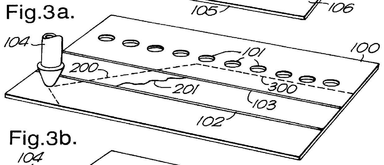
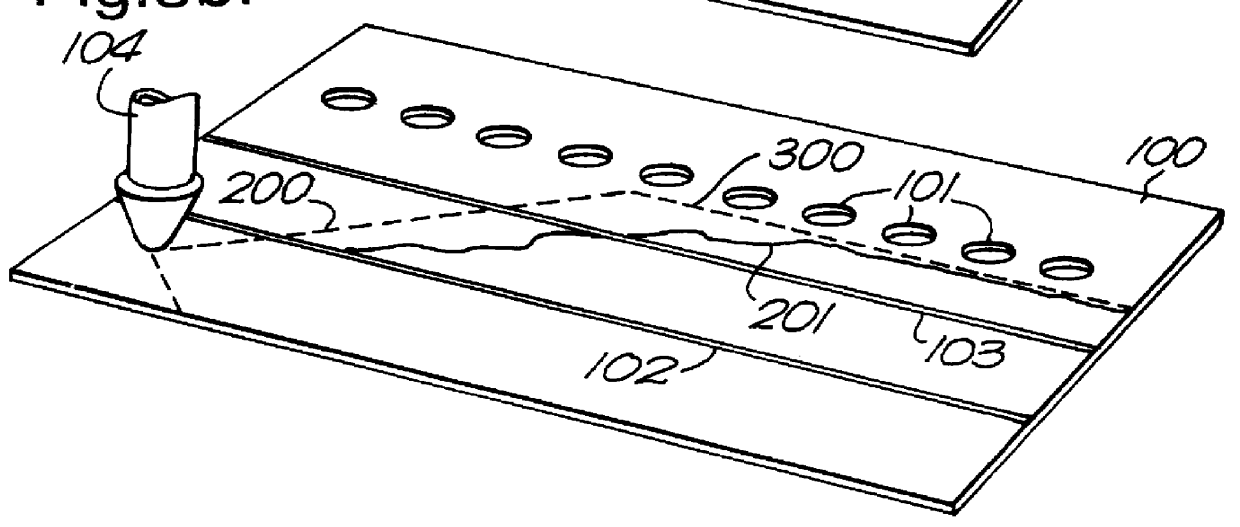
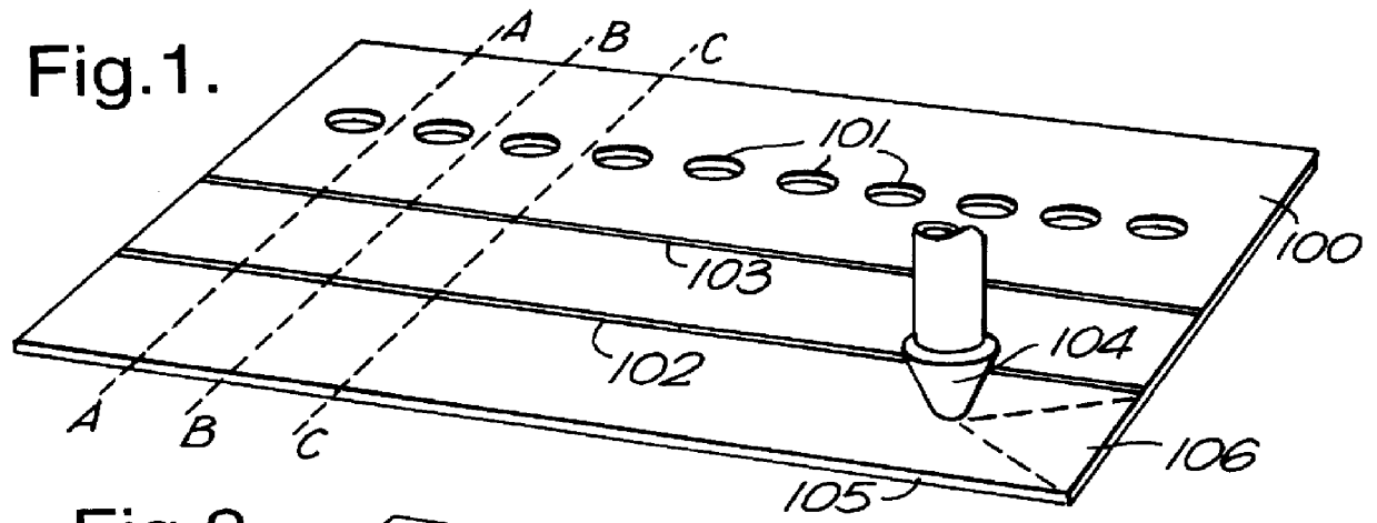
This example is described in relation to the blocking of a sheet of nitrocellulose carrier of pore size about 8 microns cast onto a backing sheet of "Mylar" polyester. The sheet is rectangular and has a length of 250 millimetres and a front-to-back width of 40 millimetres which is the intended length of an individual assay strip to be subdivided from the sheet. Each strip would have a width of about 5 millimetres. Two lines of antibody reagent have already been deposited along the entire length of the sheet using conventional reagent deposition technology such as a pen and an "XY" plotting mechanism. A first line runs parallel to the front edge of the sheet and is 8 millimetres away from the edge. This line contains a conventional murine anti-.beta. hCG monoclonal antibody deposited on the sheet as a 2.5 mg / ml solution. The second line is parallel to the first and is 16 millimetres from the front edge of the sheet. This is a control line containing a monoclonal or polyclonal antibod...


PUM

PropertyMeasurementUnit
pore sizeaaaaaaaaaa
lengthaaaaaaaaaa
lengthaaaaaaaaaa

Abstract

A process of manufacturing test strips of the type comprising a length of porous carrier material capable of acting as a liquid flow path for a sample liquid and having at least zone downstream from a first end of the strip which zone contains an immobilized specific binding agent to act as a capture means during an assay to reveal the presence of an analyte in applied sample liquid, and in which process the specific binding agent is deposited onto a sheet of the porous carrier material which is then blocked and subdivided into a plurality of individual identical test strips, wherein blocking of the porous carrier material is achieved by applying a solution of blocking agent to the sheet upstream from the zone in an amount sufficient to ensure that the solution permeates downstream to beyond the zone. Preferably there is a plurality of zones of immobilized agent arranged in series on the strip, and wherein blocking is achieved by applying a solution of blocking agent to the sheet upstream from the first of the plurality of zones in an amount sufficient to ensure that the solution permeats downstream to beyond the last of the plurality of zones.

Description

This invention relates to improved processes of manufacture of test strips.BACKGROUND TO THE INVENTIONSimple disposable assay devices, based for example on the technology described in EP-A-291194, are used extensively today in a wide variety of analytical circumstances. These include assays used in the home to detect pregnancy or fertility, and assays used in clinics and doctors offices to detect a wide range of diseases and physiological conditions. Typically these assay devices comprise a dry strip of porous material containing various reagents. The strip can be a single length of material, or can be a composite of various materials arranged in series. A sample liquid is applied to one end of the strip and while it permeates towards the other end, picks up one or more reagents and carries them into a detection zone further along the strip. There may also be a control zone, usually located downstream from the detection zone. Usually the assay result signal and the control signal ar...

Claims


Application Information

Patent Timeline
Patent Type & Authority Patents(United States)
IPC IPC(8): G01N33/52G01N33/68G01N33/76G01N33/543G01N33/558G01N33/74
CPCG01N33/521G01N33/54366G01N33/558G01N33/689G01N33/76Y10S436/81Y10S435/81Y10S435/97Y10S435/805
Inventor JOBLING, IANPERCIVAL, DAVID A.PRIOR, MICHAEL E.
Owner UNILEVER PATENT HLDG BV
Why Eureka
Try Eureka