
Means for cartilage repair

a cartilage and bone technology, applied in the field of orthopaedic research, can solve the problems of no current approach being used clinically for cartilage defects, no commercially viable treatment alternatives to date, and the success of large chondral and osteochondral defects and degenerative lesions is still a challenge for orthopaedic surgeons, so as to reduce the extraneous effect of calf serum

Inactive Publication Date: 2001-01-30
HALPERN ALAN A
View PDF2 Cites 65 Cited by
  • Summary
  • Abstract
  • Description
  • Claims
  • Application Information

AI Technical Summary

Benefits of technology

It is an object of the present invention to utilize magnetically directed growth factors, biodegradable ferromagnetic, paramagnetic, or diamagnetic polymers, and chondrocytes to successfully repair cartilage defects in a joint having cartilage defects.
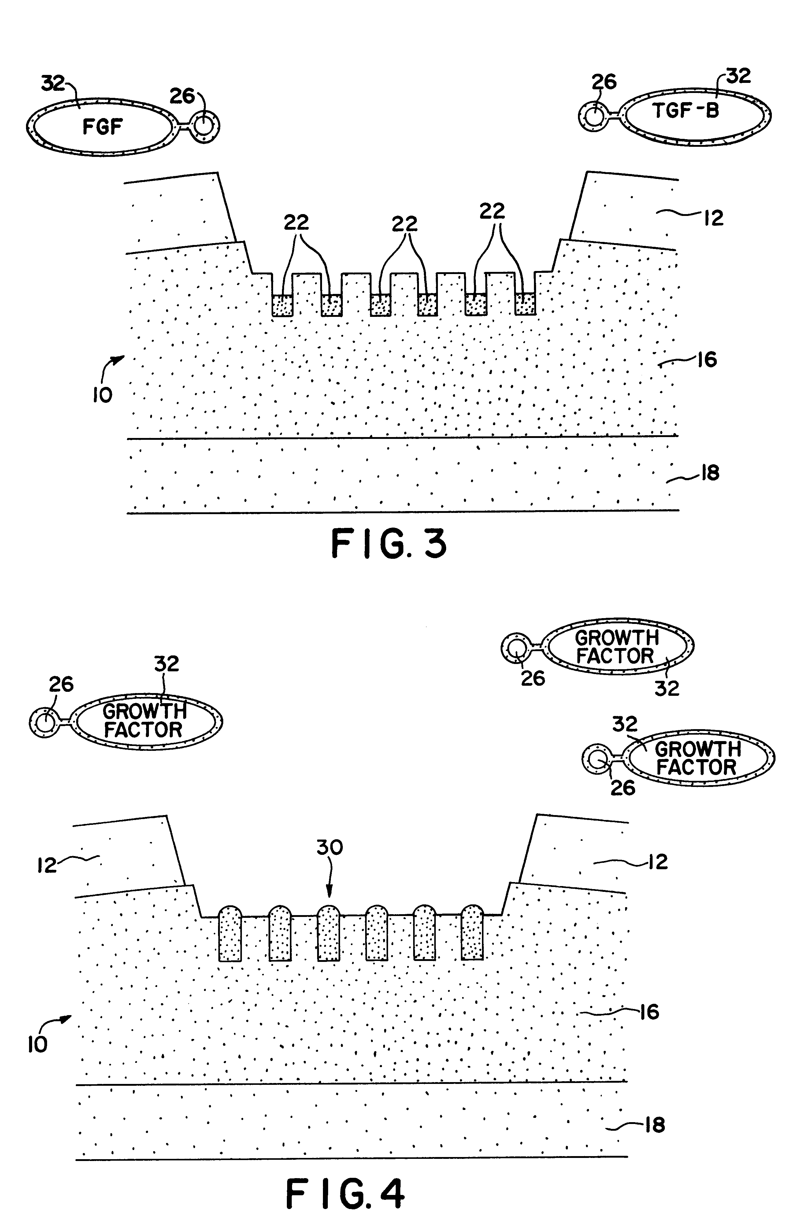
It is a primary object to provide a method for treating a patient having a cartilage defect to accomplish cartilage repair or formation by implanting a biodegradable polymer with magnetic particles, and to be able to treat the patient subsequently by sequential application of various growth factors, chondrocytes, or other growth stimulating materials to the site of the defect without the need for further major surgery.
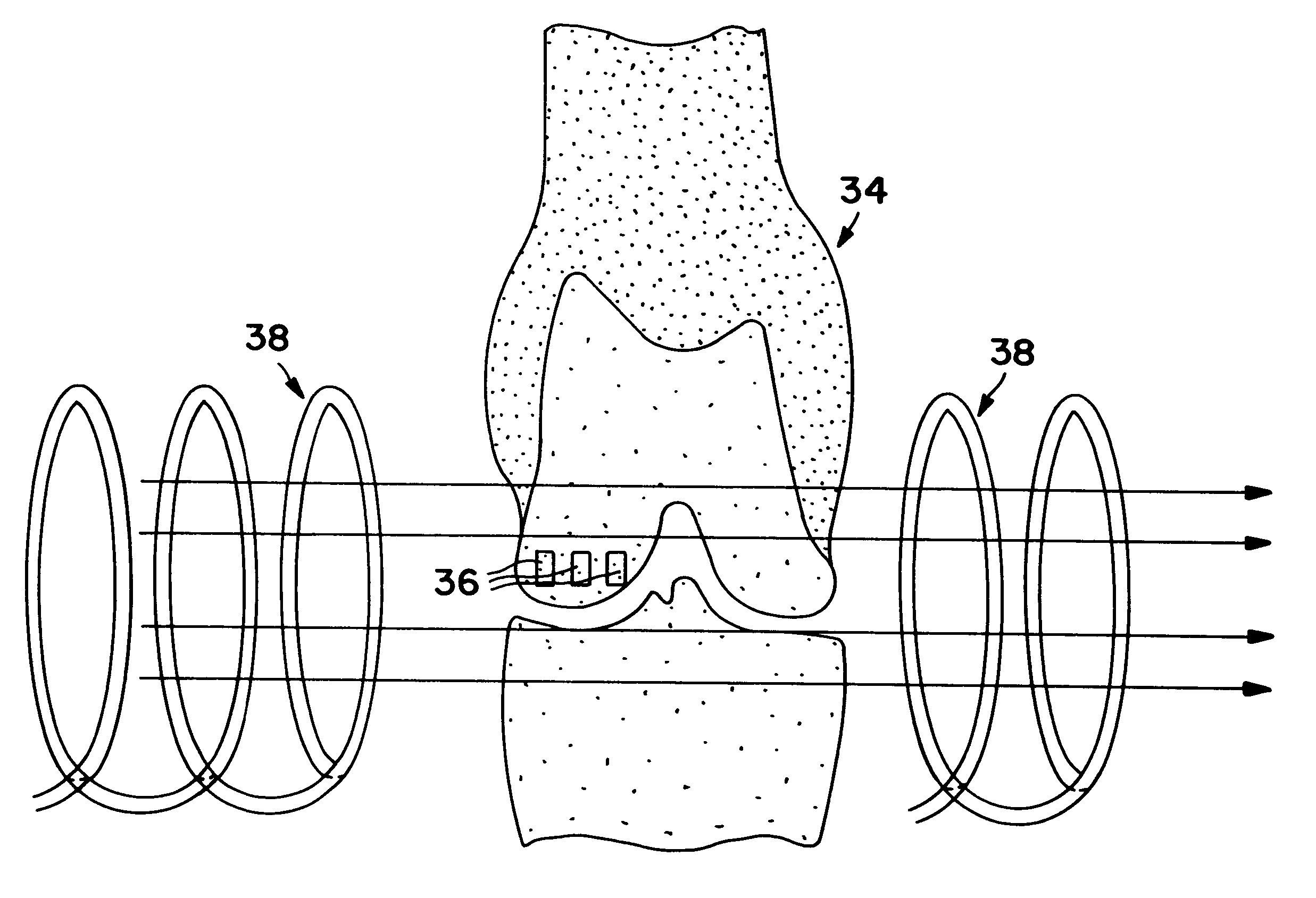
Clinical application of these principles is achieved by localization of the chondrogenic effect utilizing magnetically directed chondrogenesis. The magnetically targeted particles are directed to the cartilage defect through the implantation of ferromagnetic material in the cartilage defect area, which may involve a supplementary external magnetic field. This, while more cumbersome, offers the advantage of improved modulation of the process and pulsatile control of the implantation.
Tissue culture conditions: To prepare a three dimensional culture system, a 1% solution (W / v) of a low melting point agarose is prepared in phosphate buffered saline (PBS), and autoclaved. Upon cooling, chondrocytes or marrow cells are mixed into the still liquid solution, stirred well and then overlaid into 60 mm petri dishes. This results in an even spatial distribution of cells in a three dimensional matrix. For periosteal cultures, cooled agarose is overlaid into 60 mm petri dishes and explants of periosteal tissue are placed into the soft agarose. After six hours to allow adequate gelation, cultures are overlaid with a layer of medium. Primary cultures of periosteal cells and chondrocytes are cultured in Medium "A" as described by Osborn et al. This is a low serum formulation (50 / 50 DMEM / Hams F-12) which will minimize extraneous effects of calf serum. Cultures are fed fresh medium every other day, and examined daily for growth using an inverted phase contrast microscope.

Problems solved by technology

Even though considerable progress has been made in the field of articular reconstructive surgery, successful management of large chondral and osteochondral defects and degenerative lesions is still a challenge to the orthopaedic surgeon.
While some approaches are promising, there are currently no commercially viable treatment alternatives to date.
However, to date, despite considerable research, no current approach is actually being used clinically for treatment of cartilage defects.
To date, the data supporting this approach has not proven convincing.

Method used


Image

  • Means for cartilage repair
  • Means for cartilage repair
  • Means for cartilage repair

Examples


example 2

This example is designed to critically evaluate the ability of ferromagnetic dipoles to increase the rate of protein synthesis and proliferation in this culture system.

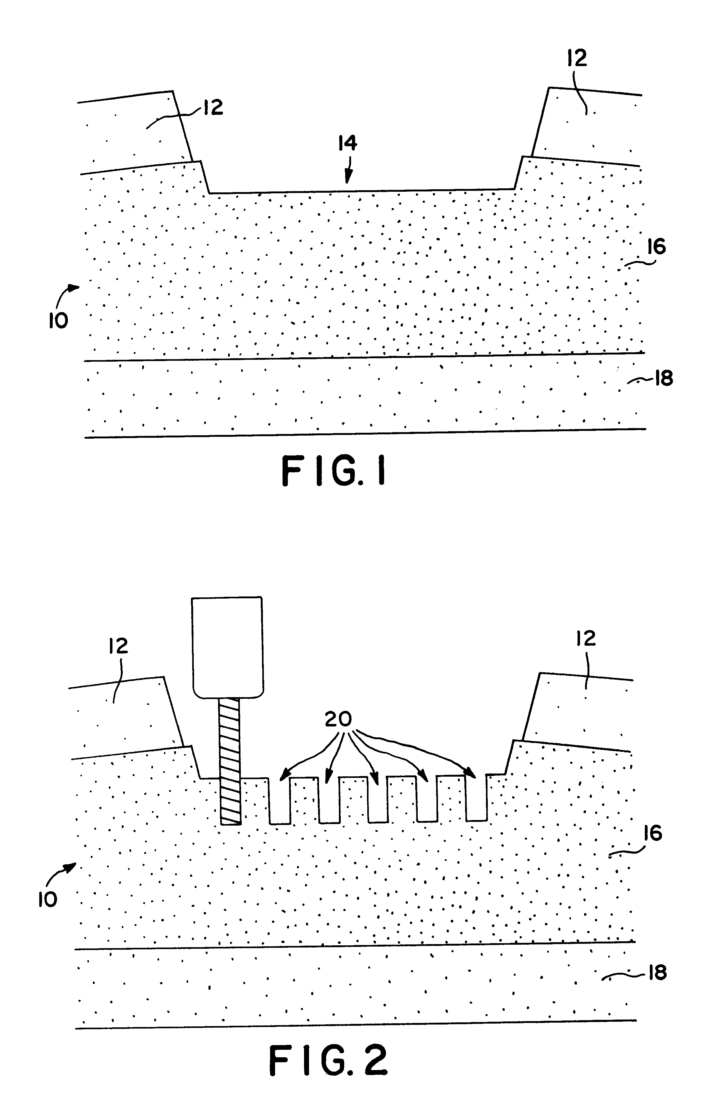
Primary cultures of periosteum tissue, marrow cells and chondrocytes are prepared and cultured as previously described. Experimental groups are prepared with ferromagnetic dipoles placed in a matrix grid pattern every 2 mm glued to the bottom of the dishes so as to be oriented perpendicular to the dish bottom. The agarose / cell suspension is then overlaid on top of the dipole array. The study is conducted in an analogous fashion to Example 1 with the following differences: Growth factor containing mediums are specially tagged to magnetic beads. Control sample are treated in a similar fashion but lack the ferromagnetic dipole array in the bottom of the petri dish.

example 3

This example is conducted in an identical fashion as Example 1 with the exception that medium supplemented with FGF alone (-TGFb) added for the first 5 days in culture. Cultures are then fed the medium containing the TGFb (3 ng / ml) and FGF is no longer used. The medium containing the TGFb is continued for a total culture time of two weeks and samples are treated as described in Example 1. The dosage of FGF used is determined from the optimal response found from the results of Example 1. Control cultures are fed med. A alone.

example 4

This example tests the reverse temporal sequence for growth factor addition as stated in Example 2. In this experiment TGFb (3 ng / ml) alone is added initially followed on a 5 day FGF. Again, samples are treated as described above with respect to dosages and controls.


PUM

PropertyMeasurementUnit
Sizeaaaaaaaaaa
Sizeaaaaaaaaaa
Pore sizeaaaaaaaaaa

Abstract

A method for repairing a defect in cartilage, comprising the provision of apertures in the cartilage by drilling holes at the base of the cartilage defect, which holes may enter the mesenchymal depot, introducing a porous scaffold material containing a plurality of magnetic particles into the apertures, and subsequently and sequentially injecting magnetically-tagged cartilage growth promoting materials such as various growth factors or chondrocytes into the area of the defect. The magnetically tagged growth promoting material is then drawn into the apertures by magnetic attraction of the magnetic particles contained in the porous scaffold material, either by virtue of the particles being permanently magnetic, or by the imposition of an external magnetic field. The present application claims the biodegradable porous scaffold material containing the plurality of magnetic particles.

Description

The present invention relates to the repair of joints of the human body, and is more particularly concerned with a method for repairing damaged cartilage and with means, especially the particular biodegradable scaffolding, utilized in carrying out the method.PRIOR ARTThe inability of adult articular cartilage for repair has been well recognized and has stimulated major interest in orthopaedic research. Even though considerable progress has been made in the field of articular reconstructive surgery, successful management of large chondral and osteochondral defects and degenerative lesions is still a challenge to the orthopaedic surgeon.Current treatment is directed at replacement of articular surfaces with total joint reconstructions when sufficient destruction has occurred. A far more preferable approach would be to remedy or replace the articular cartilage defects before progressive and debilitating arthritis has occurred.The number of individuals with symptomatic, identifiable, an...

Claims


Application Information

Patent Timeline
IPC IPC(8): A61F2/30A61K9/50A61L27/22A61L27/58A61L27/00A61L27/38A61L27/18A61L27/50A61L27/56A61F2/02A61F2/28A61F2/00A61N2/10
CPCA61F2/30756A61K9/5094A61L27/18A61L27/227A61L27/3804A61L27/3852A61L27/50A61L27/56A61L27/58C08L67/04A61F2002/2817A61F2002/30062A61F2002/30079A61F2002/30677A61F2002/30766A61F2210/0004A61F2210/009A61L2430/06Y10S623/92Y10S623/915
Inventor HALPERN, ALAN A.
Owner HALPERN ALAN A
Learn More