

Apparatus and process for manufacturing semiconductor devices, products and precursor structures utilizing sorbent-based fluid storage and dispensing system for reagent delivery
a technology of fluid storage and reagent delivery, applied in the direction of chemistry apparatus and processes, semiconductor devices, electrical devices, etc., can solve the problems of significant lag time in the dispensing operation, explosive hazard in the process system, life and operating efficiency,
- Summary
- Abstract
- Description
- Claims
- Application Information
AI Technical Summary
Benefits of technology
Problems solved by technology
Method used
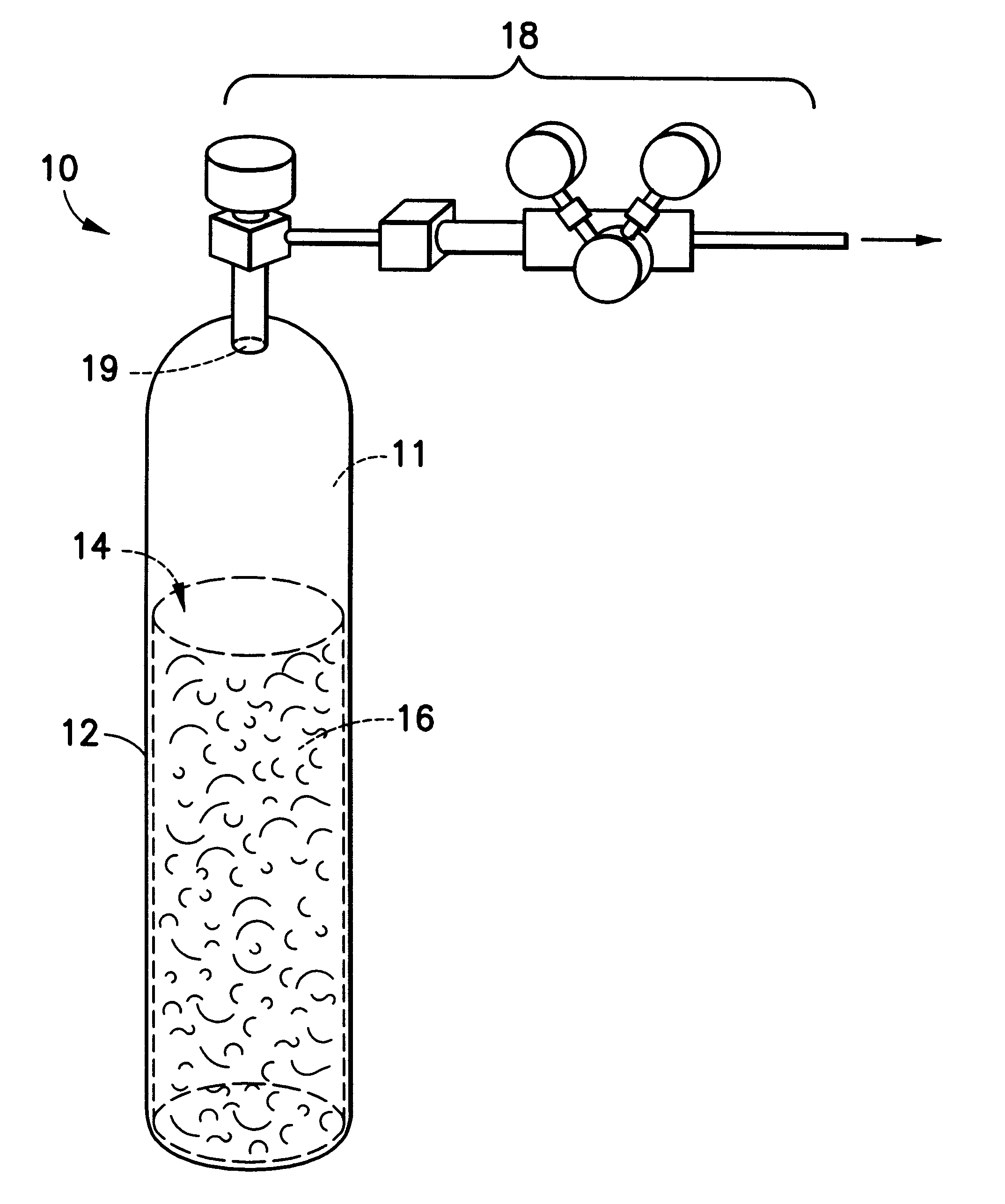
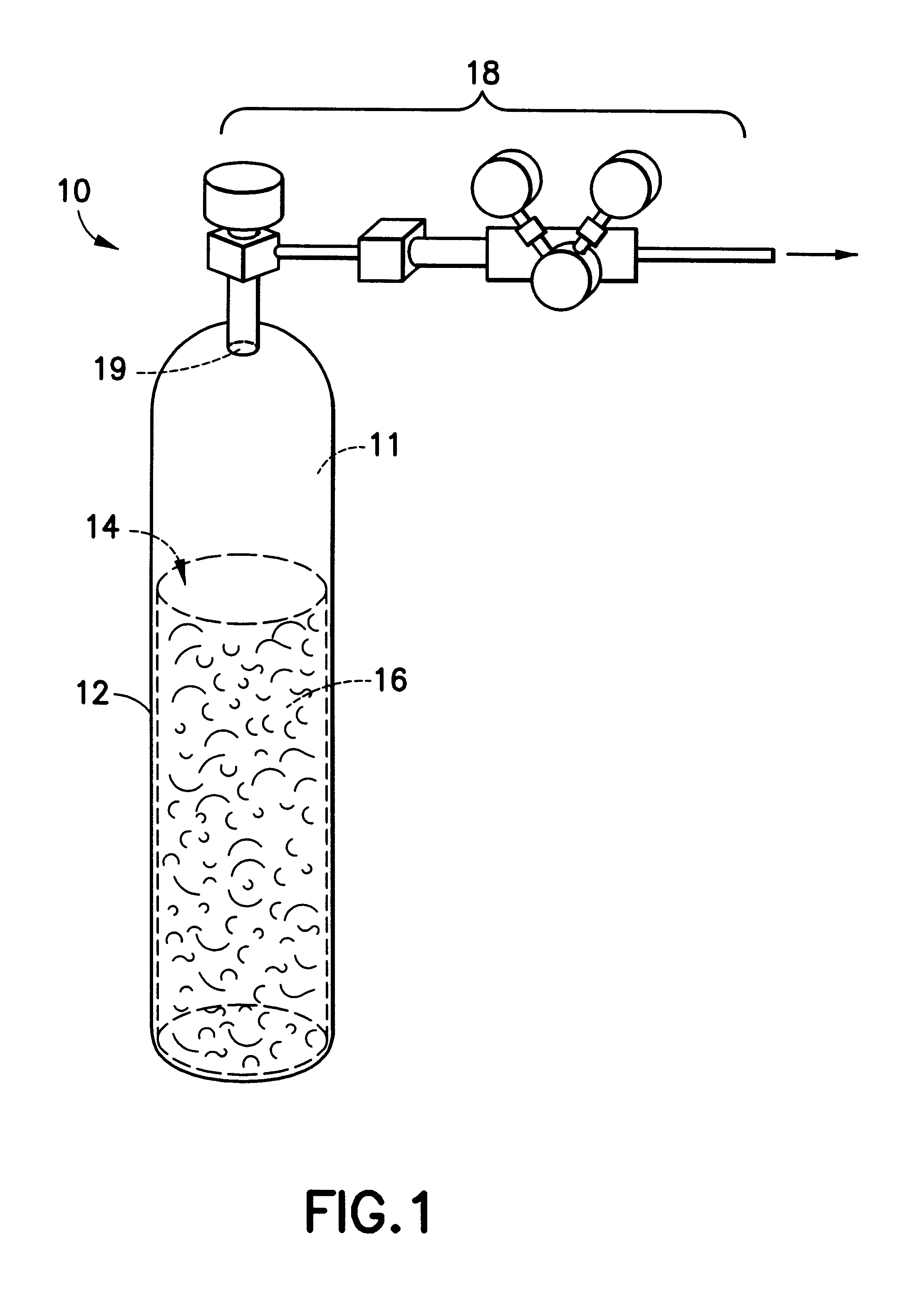
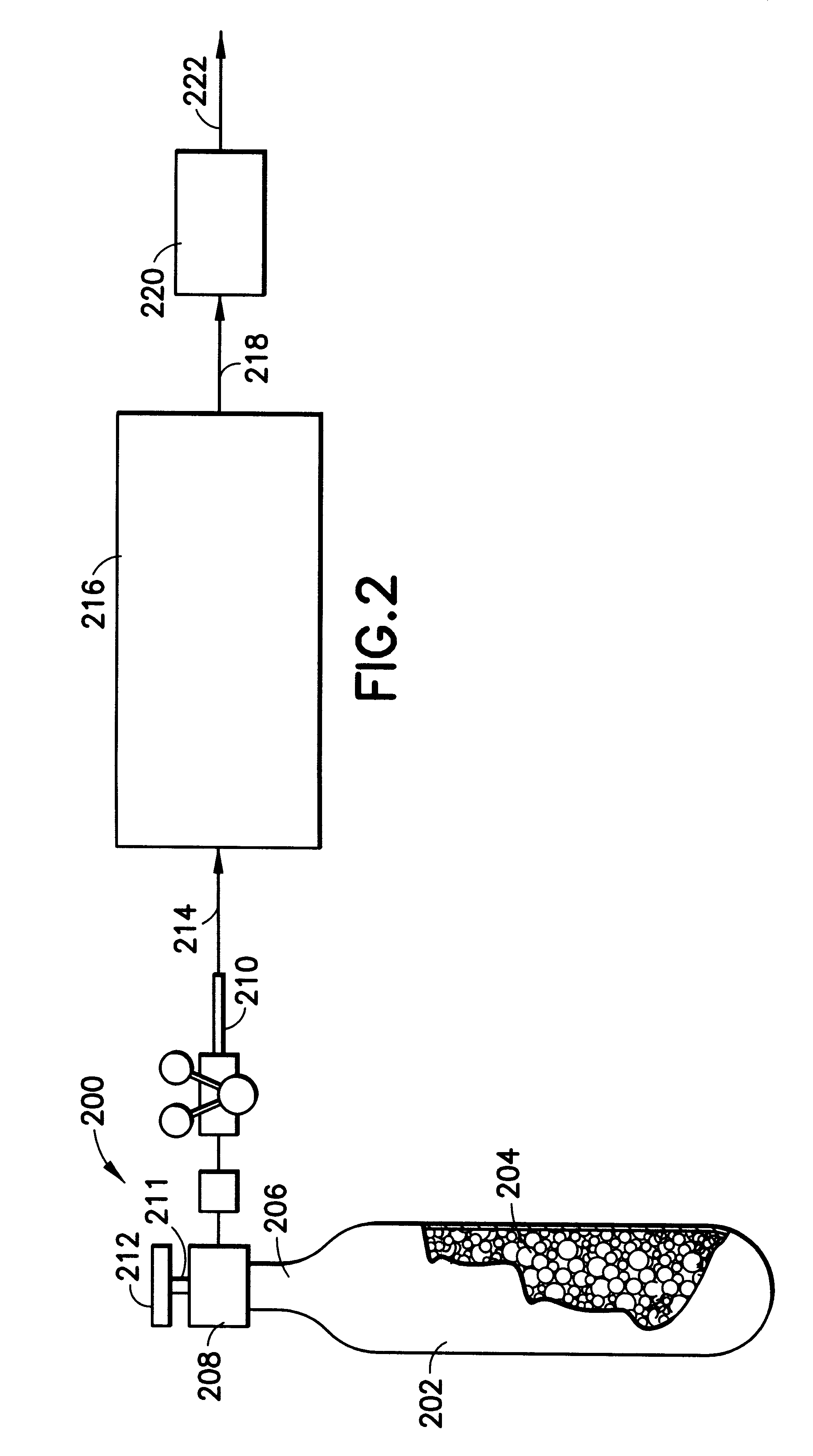
Image

Examples
Embodiment Construction
The disclosures of the following U.S. patents and applications are hereby incorporated herein by reference in their entirties:
U.S. Pat. No. 5,518,528 issued May 21, 1996 in the names of Glenn M. Tom and James V. McManus; U.S. patent application Ser. No. 08 / 650,634 filed May 20, 1996 in the names of Glenn M. Tom and James V. McManus for "Fluid Storage And Delivery System Utilizing Carbon Sorbent Medium;" U.S. Provisional Patent Application No. 60 / 046,778 filed May 16, 1997 in the names of Glenn M. Tom, Peter S. Kirlin and James V. McManus for "Semiconductor Manufacturing System Utilizing Sorbent-Based Fluid Storage and Dispensing Apparatus and Method for Reagent Delivery;" U.S. patent application Ser. No. 08 / 650,633 filed May 20, 1996 in the names of Glenn M. Tom, Karl Olander and James V. McManus for "Fluid Storage and Delivery System Comprising High Work Capacity Physical Sorbent;" U.S. patent application Ser. No. 07,742,856 filed Nov. 1, 1996 in the names of Glenn M. Tom and James...
PUM
| Property | Measurement | Unit |
|---|---|---|
| pore size | aaaaa | aaaaa |
| temperature | aaaaa | aaaaa |
| temperature | aaaaa | aaaaa |
Abstract
Description
Claims
Application Information