
Laser light optical limiter

a laser beam and optical limiter technology, applied in the field of laser beam limiters, can solve the problems of human eye, optical detectors/sensors and photo-receptors can be exposed beyond their capabilities, destroyed by either continuous or short-term laser beam exposure, and damaged retina of the ey

Inactive Publication Date: 2001-06-05
SCI MATERIALS
View PDF0 Cites 12 Cited by
  • Summary
  • Abstract
  • Description
  • Claims
  • Application Information

AI Technical Summary

Benefits of technology

It is an object of the invention to protect photo-receptors, including but not limited to a human's eyes, and optical detectors from damage by exposure to high intensity lasers by changing the transmission characteristics of a transparent inorganic material interposed between the photo-receptor and the laser.
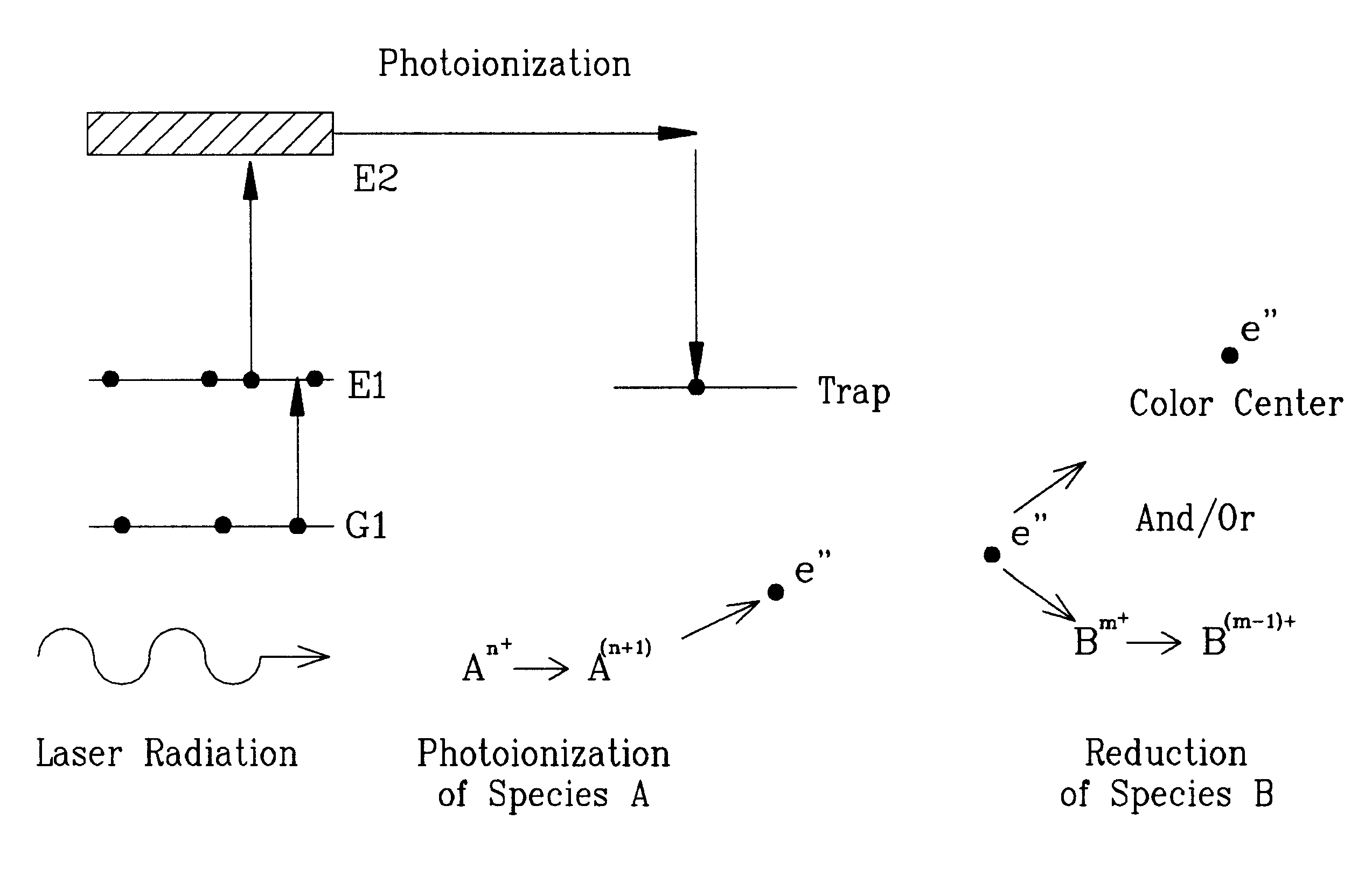
There are numerous processes in doped inorganic materials that have the capability of limiting the transmission of intense laser radiation including excited state absorption (ESA), photo-ionization, color center formation, charge transfer and trapping, and combinations of these processes. For example, at an intensity sufficient to cause damage to eyes or photo-detectors / sensors, light incident on the material is absorbed by the dopant ions that are originally in the ground state, thereby exciting the ions to an intermediate higher energy state. Ions in this intermediate energy state have substantially stronger absorption characteristics than the ions in the ground state and can further absorb light exciting the ions to even higher energy states. This process is referred to as excited state absorption. The reduction in transmission due to this process is significant when a sufficient number of ions have been excited to the intermediate level. As a result, low intensities of light pass through the material substantially unaltered while the transmission of high intensity laser light is significantly reduced. The opaque region is confined to the volume of the material which has been exposed to the high intensity laser radiation.

Problems solved by technology

The human eye, optical detectors / sensors and photo-receptors can be damaged by exposure to high intensities of light.
For example, optical detectors can be exposed beyond their capabilities and destroyed by either continuous or short duration exposure to a laser beam.
Similarly, the retina of the eye can be damaged by being exposed to a laser beam for only a brief period of time.
As a result, these protective glasses or shields typically have a disadvantage that the visual perception of the colors of objects and images observed are either altered or obscured.
This does not allow the wearer to perceive colors in the blue or green region of the visible spectrum.
Additionally, light displays projected on the wind screen or canopy and known as "heads-up" displays are color images which, if optically blocked, filtered or altered, may not be filly visible to the pilot.
The usage of lasers capable of blinding the cockpit crew of an aircraft has become a hazard for both military and commercial air traffic.
It is not feasible to block the transmission of all wavelengths of light commonly emitted by lasers using existing filtering techniques inasmuch as the ability of the pilot to observe both instrumentation inside the cockpit and other objects outside the cockpit would be so altered as to render the flight crew partially blinded or severely limited.
The reaction time of the photo-reactive elements is quite slow, on the order of 1-90 seconds, and is definitely not fast enough to provide any protection from laser beams which may be of a pulsed or continuous wave type.
Thus, a laser beam impinging on the eye through an eyeglass lens of this type will not be attenuated sufficiently or quickly enough to prevent damage to the eye.

Method used

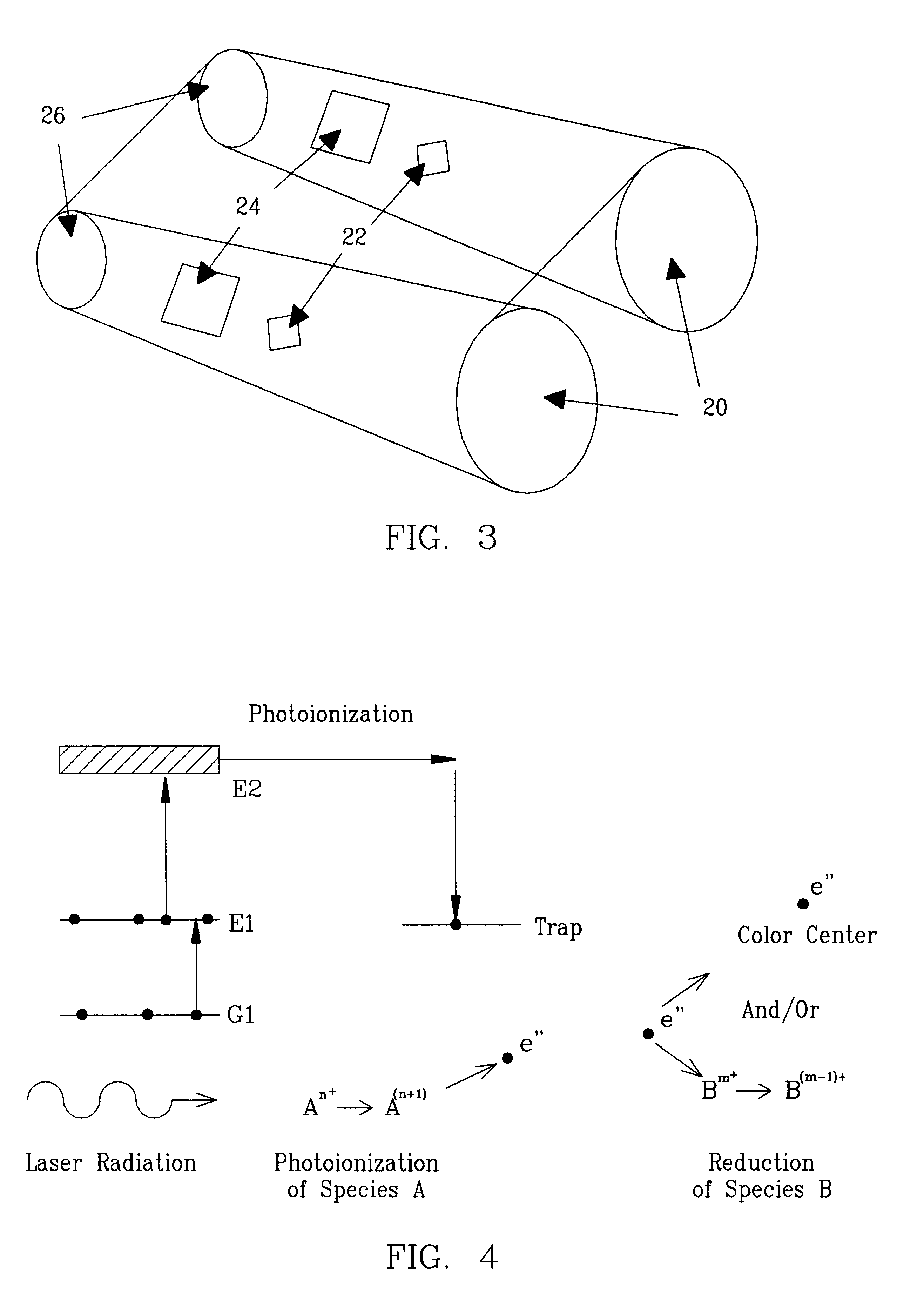

Image

  • Laser light optical limiter
  • Laser light optical limiter
  • Laser light optical limiter

Examples


Embodiment Construction

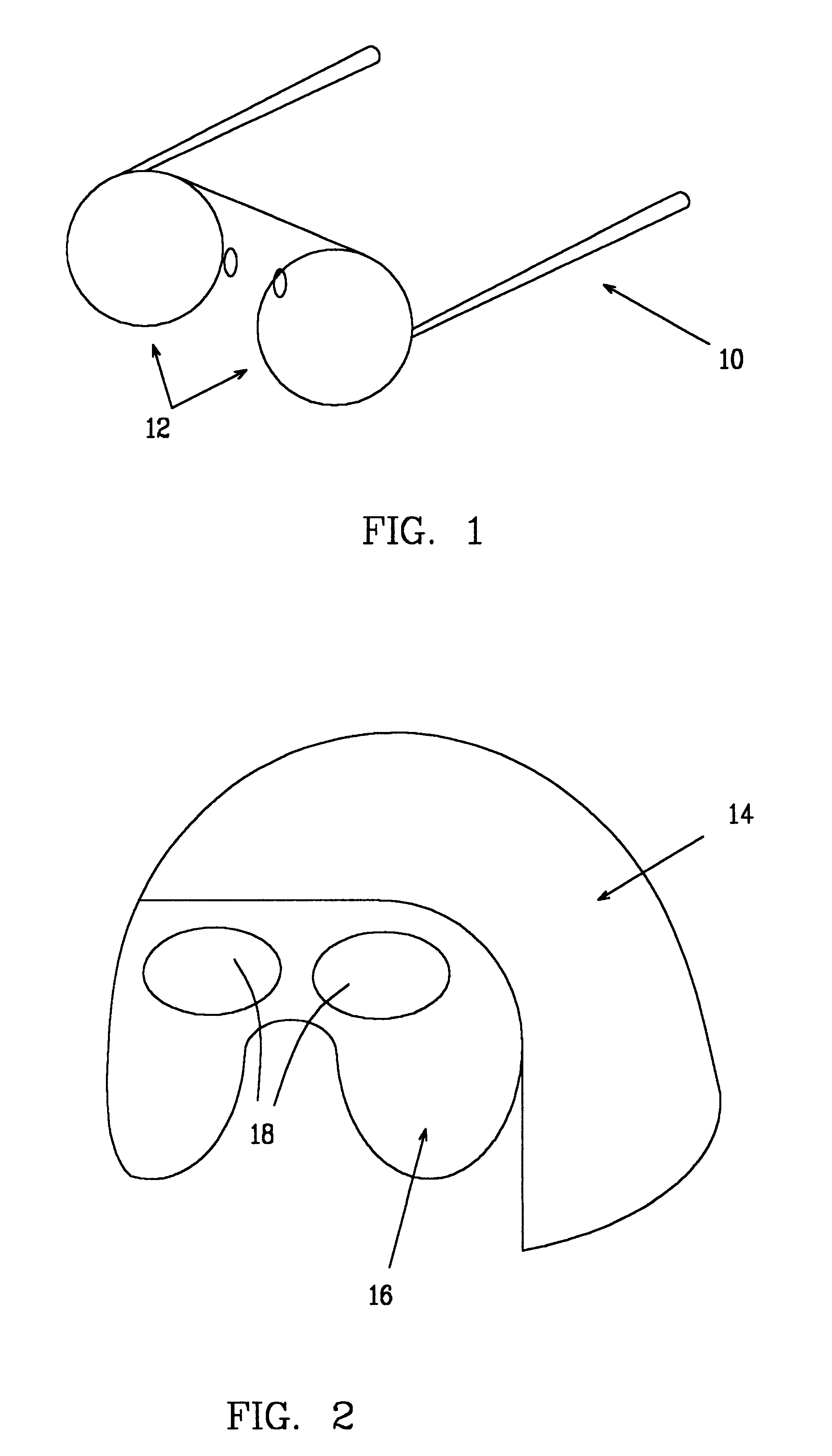
FIGS. 1 and 2 illustrate two of many forms of optical protective gear specifically and particularly available for pilots. Eyeglasses 10 have lenses 12 that may be made of the optical limiters of this invention. Lenses 12 will pass electromagnetic radiation in the visible spectrum (light) but will react to high intensity laser radiation and block the laser light. Blocking can occur as a result of numerous phenomena, two of which include: a) photo-reactive ions which undergo excited state absorption when exposed to laser radiation, and b) photo-reactive ions which photo-ionize when exposed to laser light resulting in new absorption bands which have strong absorption characteristics at the wavelength of the laser light. Similarly, the aviator helmet 14 of FIG. 2 has a visor 16, which may be fabricated of crystals 18 of this invention; or visor 16 may have crystals 18 of this invention laminated onto a visor support layer, and thus may serve as an optical limiter carrier.

In some cases, ...


PUM

PropertyMeasurementUnit
Transmissionaaaaaaaaaa
Transparencyaaaaaaaaaa
Wavelengthaaaaaaaaaa

Abstract

Inorganic crystals having one or more species of dopant ions which are photo-reactive are used as visible and or infrared light optical limiters to protect against laser radiation exposure while permitting passage of the visible and or infrared light spectrum at least until exposed to high energy laser radiation. The dopant ions are selected from ions of transition metals. The exposure of these ions within the transparent crystalline matrix either photo-ionize or are elevated to an excited state and thereby absorb or otherwise attenuate the passage of the laser beam radiation sufficiently to protect human eyes or photo-sensitive equipment. The crystals may be fabricated into such items as lenses for use in eyeglasses or on shields of flight helmets to protect the eyes of aircraft pilots.

Description

This invention relates to the protection of receptors sensitive to light in the visible and infrared (IR) regions of the electromagnetic spectrum, including but not limited to human eyes and optical detectors, and more specifically. to optical limiters, which allow passage of normal ambient light levels such as sunlight but prevent passage of high levels of light such as laser light, and which are comprised of substantially transparent material having a dopant that is photo-reactive.Visible and IR light receptors are capable of detecting electromagnetic radiation (light) at various intensity levels and at various wavelengths (colors) in the spectral region from approximately 400 nm to 5000 nm. Examples of such light receptors include but are not limited to the human eye and optical detectors / sensors which produce a response (thermal, electrical etc.) whenever illuminated.The human eye, optical detectors / sensors and photo-receptors can be damaged by exposure to high intensities of li...

Claims


Application Information

Patent Timeline
IPC IPC(8): G02B5/23G02B5/22A61B19/00A61F9/02G02F1/35
CPCG02B5/23A61B2019/409A61F9/022G02F1/3523A61B2090/049
Inventor HUTCHESON, RALPH L.EQUALL, RANDY W.
Owner SCI MATERIALS
Learn More