Method and apparatus for manufacturing magnetic recording medium

Inactive Publication Date: 2001-07-17
FUJIFILM CORP +1
View PDF11 Cites 119 Cited by
  • Summary
  • Abstract
  • Description
  • Claims
  • Application Information

AI Technical Summary

Problems solved by technology

As a result, the improvement in recording density is limited.
Namely, the output can be improved in the long wavelength region, but the output is poor in the short wavelength region.
However, the output in the long wavelength region decreases because the squareness ratio in the vertical direction cannot be increased to the desired value.
However, it is difficult in this method to generate a magnetic field having a small angle to the surface of the magnetic layer and, therefore, the magnetic powder particles cannot be oriented in the desired oblique direction.
Further, since this method requires the positions of the pair of magnets to be changed so as to interpose the magnetic recording medium therebetween in accordance with the angle at which magnetic powder particles are to be oriented, the apparatus inevitably becomes large.
Moreover, since the magnets are disposed at a predetermined angle to the surface of the magnetic layer, the area where the magnetic powder particles are oriented is small and, therefore, it is impossible to efficiently produce a magnetic recording medium having a high squareness ratio in a desired oblique direction.
Therefore, if the time period for orientation is made sh

Method used


Image

  • Method and apparatus for manufacturing magnetic recording medium
  • Method and apparatus for manufacturing magnetic recording medium
  • Method and apparatus for manufacturing magnetic recording medium

Examples


example 1

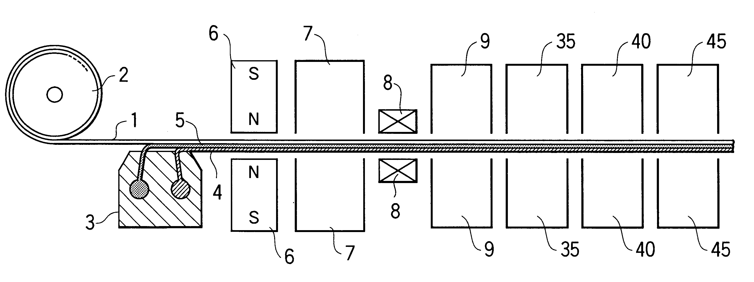
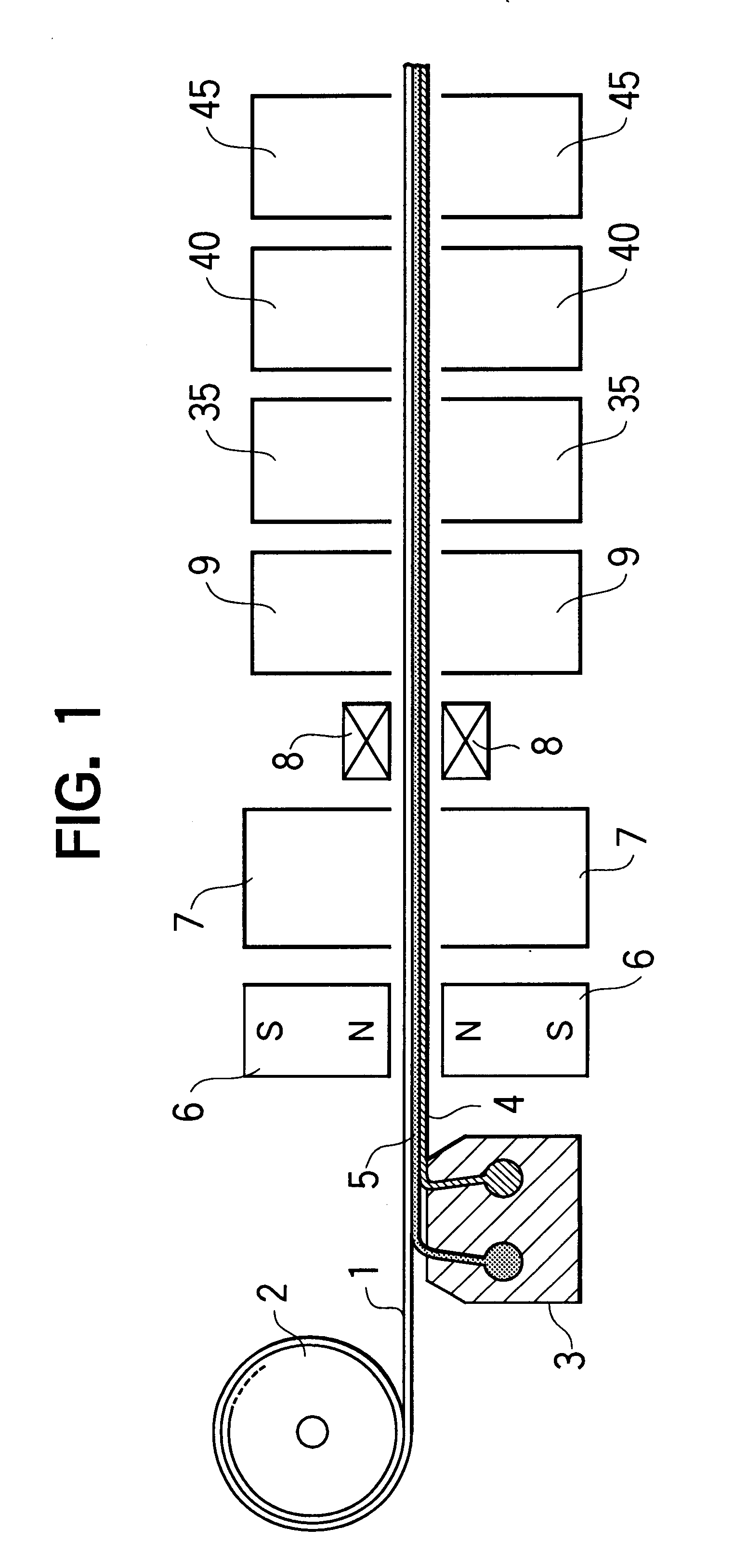
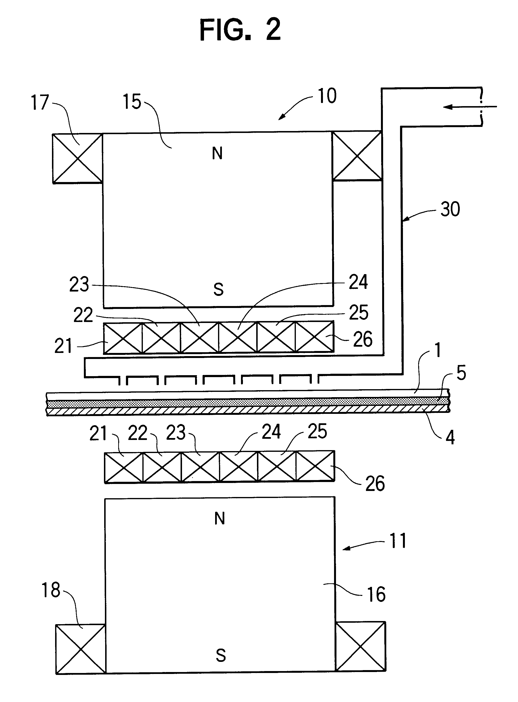
Magnetic recording media were manufactured using the apparatus for manufacturing a magnetic recording medium shown in FIGS. 1 and 2.

A magnetic coating solution for an upper magnetic layer and a non-magnetic coating solution for a lower non-magnetic layer having the following compositions were simultaneously applied onto the surface of a web-like polyethylene terephthalate film having a width of 500 mm and a thickness of 10 .mu.m using an extrusion-type simultaneous multiple coating device having two slits so that the dried thickness of the upper magnetic layer would be 0.2 .mu.m and that of the lower non-magnetic layer would be 1.5 .mu.m, thereby forming the upper magnetic layer and the lower non-magnetic layer.

A magnetic field of 7500 Oe was applied onto the upper magnetic layer and the lower non-magnetic layer by a pair of permanent magnets disposed with their N poles facing each other, thereby orienting the magnetic powder particles contained in the upper magnetic layer in the lo...

example 2

Magnetic recording media were manufactured in the same manner as in Example 1 except that the preliminary drying was not effected and the squareness ratios were measured in the same manner as in Example 1. The results of the measurement are shown in Table 2.

example 3

Magnetic recording media were manufactured in the same manner as in Example 1 except that the longitudinal orientation by the pair of permanent magnets was not effected and the squareness ratios were measured in the same manner as in Example 1. The results of the measurement are shown in Table 2.


PUM

PropertyMeasurementUnit
Fractionaaaaaaaaaa
Angleaaaaaaaaaa
Angleaaaaaaaaaa

Abstract

A method for manufacturing a magnetic recording medium includes steps of forming a magnetic layer containing magnetic powder particles on a web-like non-magnetic support being continuously transported in one direction and applying a magnetic field to the magnetic layer by a plurality of magnets in such a manner that an angle of the magnetic field applied to the magnetic layer to the transporting direction of the non-magnetic support in a plane perpendicular to a surface of the magnetic layer and parallel to the transporting direction of the non-magnetic support gradually increases in the transporting direction of the non-magnetic support, thereby orienting the magnetic powder particles in an oblique direction with respect to the surface of the magnetic layer. According to this method, it is possible to orient magnetic powder particles in a desired direction with respect to the surface of a magnetic layer and to manufacture a magnetic recording medium having a high squareness ratio without increasing the size of the apparatus.

Description

The present invention relates to a method for manufacturing a magnetic recording medium and an apparatus therefor, and, in particular, to a method for manufacturing such a medium by orienting magnetic powder particles contained in a magnetic layer thereof in an oblique direction with respect to the surface of the magnetic layer and an apparatus therefor.DESCRIPTION OF THE PRIOR ARTConventionally, a web-like magnetic recording medium has been manufactured by orienting magnetic powder particles contained in a magnetic layer thereof in a direction parallel to the surface of the magnetic layer and in the longitudinal direction of the magnetic recording medium.However, in the case where magnetic powder particles are oriented in the longitudinal direction of a magnetic recording medium, the demagnetization field in the medium becomes greater. As a result, the improvement in recording density is limited. Namely, the output can be improved in the long wavelength region, but the output is po...

Claims


Application Information

Patent Timeline
IPC IPC(8): G11B5/845
CPCG11B5/845
Inventor KOMATSU, KAZUNORISHIBATA, NORIO
Owner FUJIFILM CORP
Why Eureka
Try Eureka