Frequency converter with improved linearity

a linearity and frequency converter technology, applied in the direction of demodulation, oscillation generators, electrical apparatus, etc., can solve problems such as inability to filter interference, and achieve the effect of improving linearity

Inactive Publication Date: 2001-08-21
APPLE INC
View PDF8 Cites 23 Cited by
  • Summary
  • Abstract
  • Description
  • Claims
  • Application Information

AI Technical Summary

Benefits of technology

An object of the invention is to provide a novel frequency converter for converting a signa

Problems solved by technology

However, the third order terms comprising the second harmonic of one tone and the fundamental frequency of

Method used


Image

  • Frequency converter with improved linearity
  • Frequency converter with improved linearity
  • Frequency converter with improved linearity

Examples


Embodiment Construction

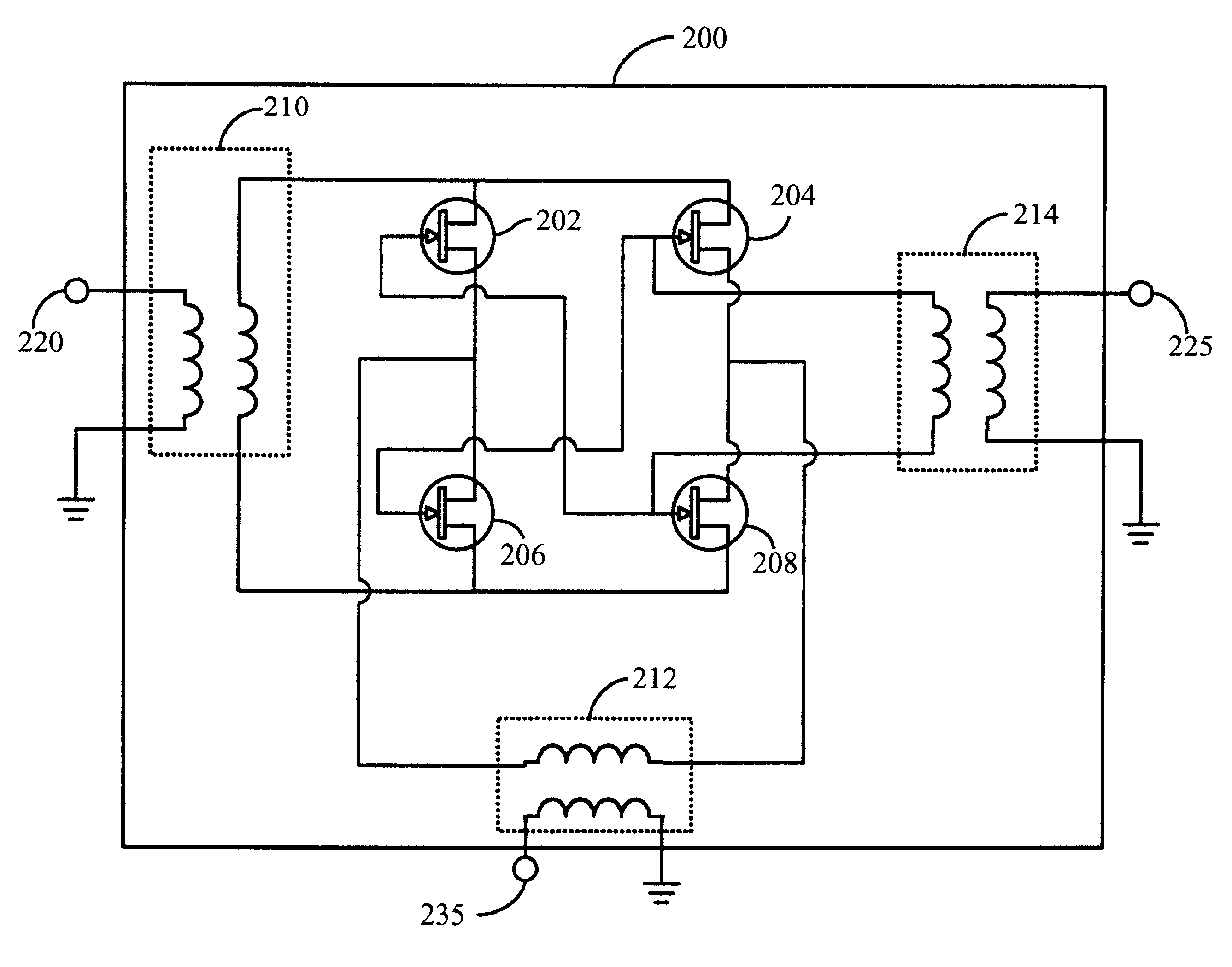
The main purpose of a MESFET mixer is to convert a signal from an RF signal to a lower frequency signal as efficiently as possible. That is, the sinusoidal input has to be reproduced at the output as accurately as possible but at a frequency that can be processed by other electronic components.

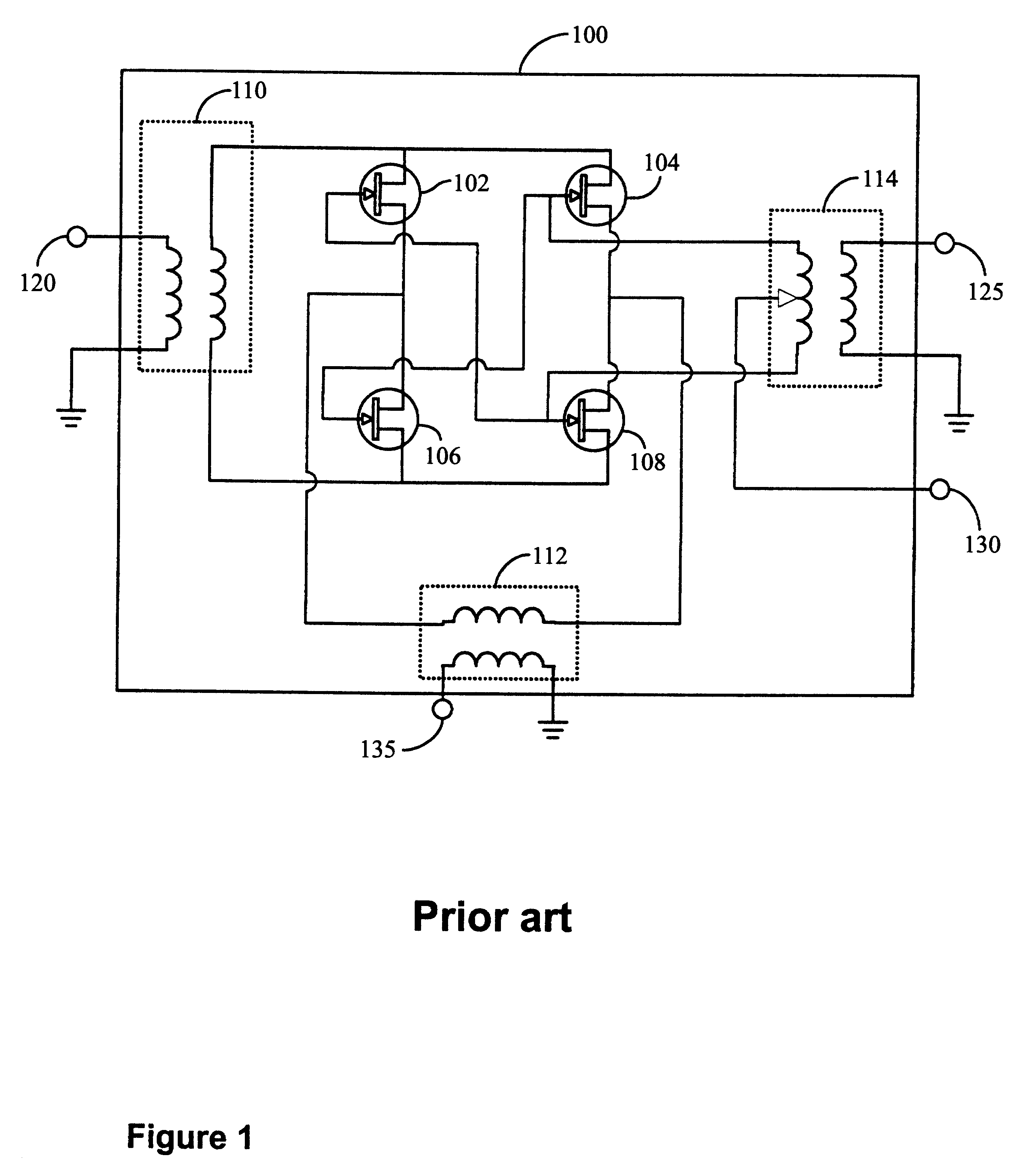
FIG. 1 shows a circuit diagram of a typical prior art double-balanced MESFET mixer 100. Three inputs are required in mixer 100. The first input 120 is the RF signal (of sinusoidal form) as received from the air medium. The second input 125 is a signal provided by a Local Oscillator (LO) of the communications receiver (not shown). The LO signal may be a clipped sine wave or a square wave. The third input 130 is a DC bias that is applied to the gates of the four MESFETs (102, 104, 106 and 108). In a specific embodiment of the prior art mixer, the gate bias voltage is -1.4V.

The output 135 is an intermediate frequency signal (lower than RF) that can be demodulated by other electronic components in...


PUM


Abstract

A frequency converters used in communications receivers. Such frequency converters can be used for converting a signal from a Radio Frequency (RF) to a low frequency suitable for processing such as demodulation. The inventors have made the unexpected discovery that when the gates of the MESFETs of a double-balanced mixer are left open-circuited and allowed to self-bias, the drop in mixer linearity at high LO power levels is reduced thereby increasing the LO power range of operation. This invention can be used as an improved scale-down mixer as well as an upconverter mixer.

Description

The present invention relates to frequency converters used in communications receivers. Such frequency converters can be used for converting a signal from a Radio Frequency (RF) to a low frequency suitable for processing such as demodulation or vice versa.Frequency converters, more commonly called "mixers", are employed in communication receivers. They are used for converting an RF signal, transmitted over the air medium, to a lower frequency signal suitable for demodulation in a receiver. Double-balanced Metal-Semiconductor Field Effect Transistor (MESFET) mixers are frequently used in RF receivers. Double-balanced mixers are well-known to those skilled in the art and the reader is invited to consult "Microwave Mixers", Second Edition, Norwood, Mass., Artech House, 1993, pp. 333-369, by S. A. Maas for further information on this subject. This document is hereby incorporated by reference.One of the parameters of a mixer is its linearity, which can be defined as the level or correlat...

Claims


Application Information

Patent Timeline
IPC IPC(8): H03D7/14H03D7/12H03D7/00
CPCH03D7/14H03D7/125
Inventor POULIN, GRANT DARCYRABJOHN, GORDON G.NISBET, JOHN J.
Owner APPLE INC
Why Eureka
Try Eureka