Apparatus and methods for performing acoustical measurements

a technology of acoustic measurement and an apparatus, applied in the field of acoustic measurement, can solve the problems of insufficient accuracy of the approach, and inability to accurately predict the pick-up rate of bubblers

Inactive Publication Date: 2001-08-28
VEECO INSTR
View PDF27 Cites 76 Cited by
  • Summary
  • Abstract
  • Description
  • Claims
  • Application Information

AI Technical Summary

Benefits of technology

It is another object of the invention to provide improved methods and apparatus for performing pulse acoustical measurements on a gas mixture, e.g., a binary gas mixture. As discussed below, one aspect of achieving this object involves measuring the propagation time between two chosen received signals. In this way, the measured acoustic signals have the same electronic and acoustic paths. Advantages which derive from this approach include enhanced repeatability and the absence of drift.
Other aspects of improving pulse acoustical measurement techniques include using high frequencies in the range from 0.5 to 10 MHz which allow for the achievement of high resolution of the received signals, a high sampling rate, and small dimensions of the sensor. In particular, frequencies in this range allow the system to have both a practical sensor size and to operate in the near field zone with plane waves whose divergence coefficient is essentially zero.

Problems solved by technology

This approach suffers from insufficient accuracy due to, among other things: variations in the bubbler temperature; instability of the temperature and pressure of the binary gas mixture; possible leakages in the gas lines upstream and downstream of the bubbler; and concentration time delays between the mass flow controllers and the points of interest, especially at low flow rates.
In addition, the existing equations used to predict a bubbler's pick-up rate are inaccurate.
None of these approaches fulfill all the requirements for a binary gas measuring system, including robustness, maintenance free operation, and the ability to produce highly accurate and repeatable real time concentration measurements of high purity and / or highly corrosive gaseous media.
The pulse approach as practiced in the prior art has generally been less accurate than the phase approach.
UFFC-34, No. 1, January 1987, 8-16), but their capabilities are very weak for concentration measurements in gaseous media.
Such a device thus requires continuous maintenance.
These effects are capable of producing incorrect values for the speed of sound, and, in turn, incorrect concentration measurements.
None of the prior art acoustical methods perform satisfactory at present.
In particular, none of these methods are able to fully meet the fundamental requirements of providing highly accurate concentration measurements without the need for frequent maintenance.
There are a variety of sources of significant error in acoustical concentration measurements.
(1) Ambiguities in the existing mixing rules used to calculate concentrations from measured values of the speed of sound.
It can also cause errors in the evaluation of the specific heat capacities used in these equations.
This problem of compressibility, of course, is much more complicated for a gas mixture since rules for determining the compressibility factor of a gas mixture have not been reported in the literature.
(2) Lack of known thermodynamic properties for many gases.
Very often, however, the coefficients have not been published and, indeed, even the manufacturer of the chemical of interest may not have the information needed to estimate the coefficients.
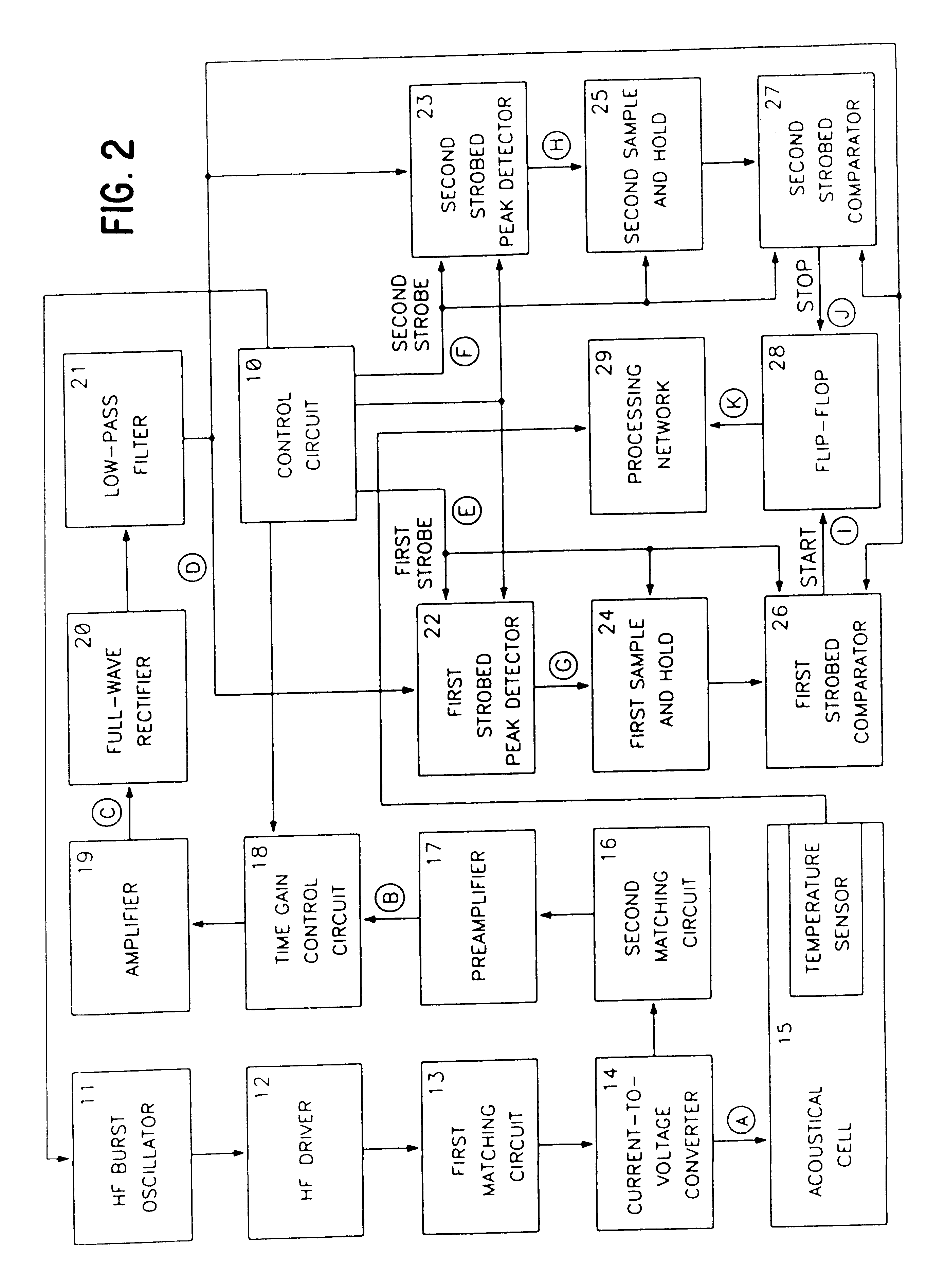
(3) Insufficient accuracy of existing methods and apparatus for measuring the speed of sound in a gas mixture.
The use of separate transducers, however, does have a significant disadvantage which has not been effectively addressed in the prior art.
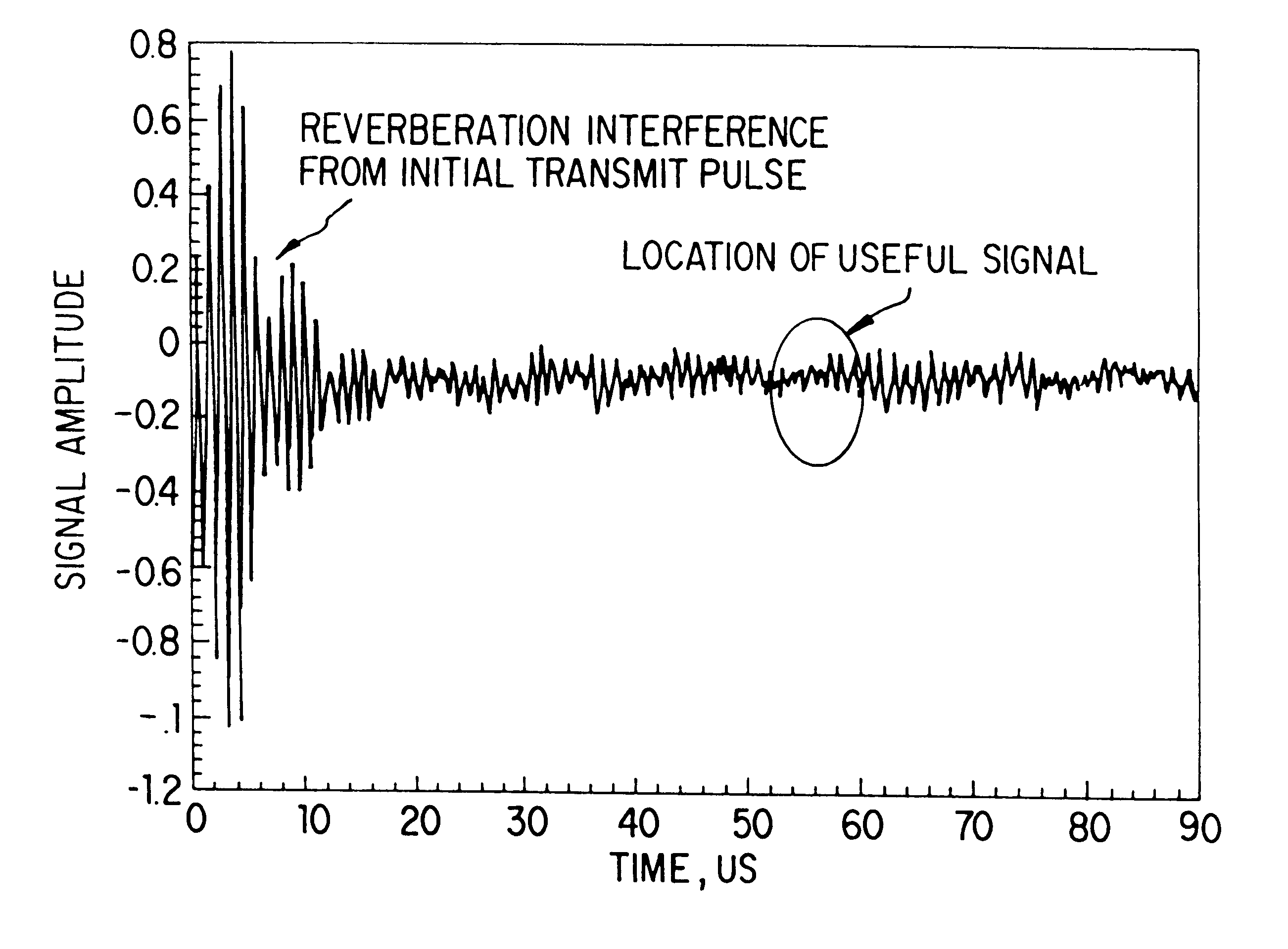
(a) Spectrum distortion and time delay of the first half-wave of the received signal in the piezoelements, in the transfer layers between the piezoelements and the gaseous medium, and in the electronic networks of the transmitter and receiver. Since these distortions and delays are constant for any given hardware system, this type of systematic error can at least in theory be compensated for during calibration using an ideal or near ideal gas, provided the distance between the two transducers is known to within a few micrometers.
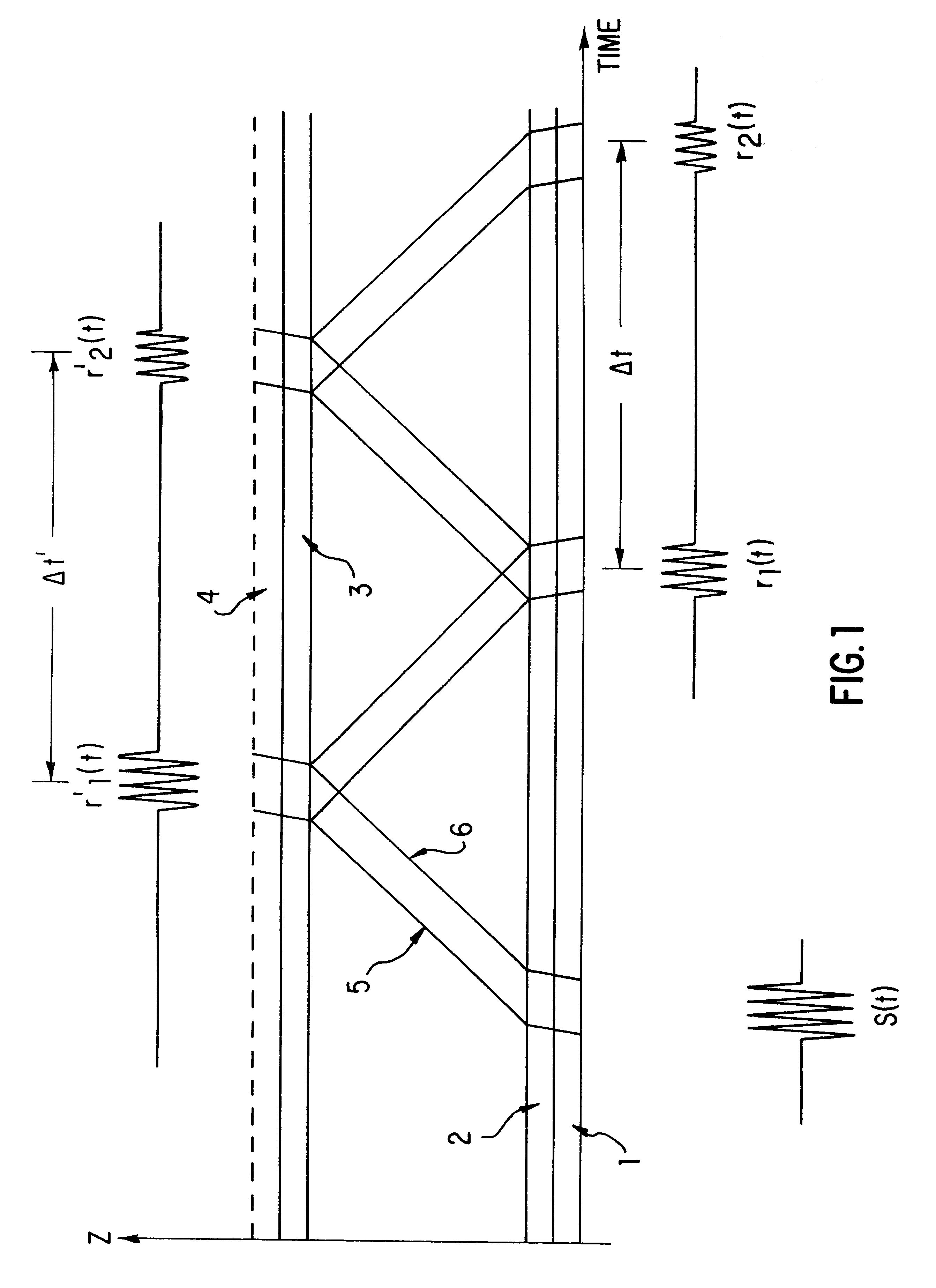
(b) Spectrum distortion of the first half-wave of the received signal as result of operating under far-field conditions as is normally done for systems using the shadow method. That is, the transmitter and the receiver are spaced from one another by an acoustical path length L.sub.p which satisfies the relationship: ##EQU9##
Plainly, this type of systematic error is dependent upon the acoustical properties of the gases in the mixture as well as their concentrations, and thus cannot be compensated for during calibration.
Once again, this type of systematic error cannot be compensated for during calibration.
(d) Spectrum distortion of the first half-wave of the received signal due to side wall reflection interference.
Their reduction is possible only by frequent re-calibration of the instrument with different gases at different concentrations and temperatures, which is clearly undesirable.
From the foregoing, it can be seen that the existing techniques for performing acoustical measurements suffer from numerous drawbacks and limitations.
In particular, all the existing acoustical concentration measurement methods and instruments require frequent maintenance to reduce the total error introduced by different recipes, as well as by temperature and pressure variations.
In addition, these techniques are associated with significant inaccuracies and ambiguities in the concentration measurement, which limit their usefulness in producing highly accurate and reliable measurements.

Method used


Image

  • Apparatus and methods for performing acoustical measurements
  • Apparatus and methods for performing acoustical measurements
  • Apparatus and methods for performing acoustical measurements

Examples


example

This example compares the results of using the mixing rule of equation (56) of the present invention with that of equation (7) of the prior art in determining the concentration of a gas of interest in a binary mixture from a speed of sound measurement performed on the mixture. For purposes of illustration, the binary mixture has been assumed to comprise trans-1,2-dichloroethylene (the gas of interest) and nitrogen (the carrier gas). The thermodynamic and mechanical properties of both these gases are well known.

The results of the comparison are shown in FIG. 30, where the solid curve is based on the mixing rule of equation (56) and the dashed curve on that of equation (7). The measured speed of sound for a mixture of trans-1,2-dichloroethylene (DCE) and nitrogen produced by a bubbler system operating at a temperature of 20.degree. C. and a pressure of 760 torr is 242.54 m / s. From FIG. 30, we can see that this speed of sound corresponds to a G.sub.DCE / G.sub.N2 ratio of 1.8271 when th...


PUM

PropertyMeasurementUnit
speedsaaaaaaaaaa
frequenciesaaaaaaaaaa
particle sizeaaaaaaaaaa

Abstract

Apparatus (15, 30) and methods for performing acoustical measurements are provided having some and preferably all of the following features: (A) the system (15, 30) is operated under near-field conditions; (B) the piezoelement (40) or piezoelements (40, 48) used in the system are (i) mechanically (41, 49) and electrically (13, 16) damped and (ii) efficiently electrically coupled to the signal processing components of the system; (C) each piezoelement (40, 48) used in the system includes an acoustical transformer (42, 50) for coupling the element to a gaseous test medium (9); (D) speed of sound is determined from the time difference between two detections of an acoustical pulse (81, 82) at a receiver (40, FIG. 3; 48, FIG. 7); (E) cross-correlation techniques are employed to detect the acoustical pulse at the receiver; (F) forward and inverse Fourier transforms employing fast Fourier transform techniques are used to implement the cross-correlation techniques; in such a mathematical manner that the peak of the cross-correlation function corresponds to the detection of a pulse at the receiver and (G) stray path signals through the body (31) of the acoustic sensor (15, 30) are removed from detected signals prior to signal analysis. Techniques are also provided for performing acoustical measurements on gases whose thermodynamic properties have not been measured and on mixtures of compressible gases. Methods and apparatus (29) for performing feedback control of a gas of interest in a mixture of that gas and a carrier gas are provided in which the controlled variable is the flow of the carrier gas.

Description

I. FIELD OF THE INVENTIONThis invention relates generally to the field of acoustical measurements performed on gases, liquids, and solids. More particularly, in accordance with certain of its aspects, the invention relates to new and improved methods of, and apparatus for, acoustically testing a gas mixture to measure gas concentrations, volumetric flow ratios, and / or mass flow ratios. In accordance with other aspects, the invention relates to the determination and / or the control of the mass (or volume) flow rate of a gas of interest in a carrier gas, where the carrier gas has a known flow rate.II. BACKGROUND OF THE INVENTIONA. Industrial SettingNumerous industries employ processes which require accurate delivery of a binary gas mixture consisting of a gas of interest and a carrier gas. To achieve accurate delivery, these industries require precise measurements of the concentration of the gas of interest in the flowing gas mixture, where the gas of interest is typically of high puri...

Claims


Application Information

Patent Timeline
Patent Type & Authority Patents(United States)
IPC IPC(8): G01N29/02G01N29/22G01N29/44G01N29/46G01N29/50G01N29/024
CPCG01N29/024G01N29/222G01N29/449G01N29/50G01N29/46G01N2291/102G01N2291/02809
Inventor LOGUE, RAYMOND C.SIROTA, DON N.LEE, PATRICK S.
Owner VEECO INSTR
Why Eureka
Try Eureka