Anodization of magnesium and magnesium based alloys

anodization and magnesium based alloy technology, applied in the field of building industry, can solve the problems of high current usage, significant heat absorption by the bath itself, easy discoloration of both materials, etc., and achieve the effect of adding corrosion resistan

Inactive Publication Date: 2001-08-28
MAGNESIUM TECHNOLOGY LIMITED
View PDF11 Cites 122 Cited by
  • Summary
  • Abstract
  • Description
  • Claims
  • Application Information

AI Technical Summary

Benefits of technology

Therefore, it is an object of the present invention to provide a method for the anodization of magnesium or magnesium alloys which will provide a coating similar to anodized aluminum, add corrosion resistance and / or overcome some of the disadvantages of the prior art and / or at least provide the public with a useful choice.
Thus it can be seen that the process and the products from the process may provide significant advantages over the prior art methods and products.

Problems solved by technology

Both materials easily discolor upon exposure to the atmosphere through oxidization.
The use of sparks throughout the process leads to a relatively high current usage and to significant heat absorption by the bath itself.
Therefore, any commercial anodization plant requires substantial cooling equipment to reduce the temperature of the bath through the use of this process.
However, the coating is not a direct visual comparison with anodized aluminum and, therefore, has a problem matching other components made from anodized aluminum.
These are extremely hazardous materials causing fume and safety problems to the plant operators, and disposal problems.

Method used


Image

  • Anodization of magnesium and magnesium based alloys
  • Anodization of magnesium and magnesium based alloys

Examples


example 2

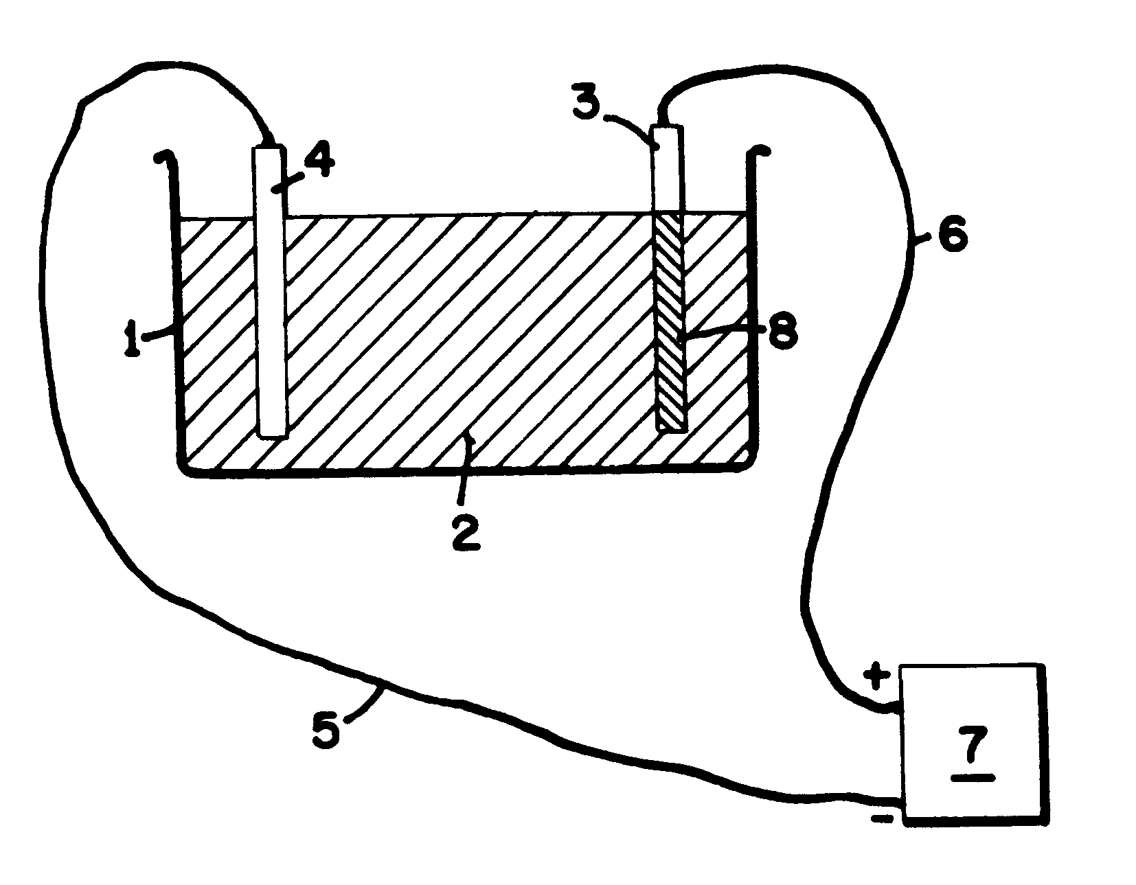
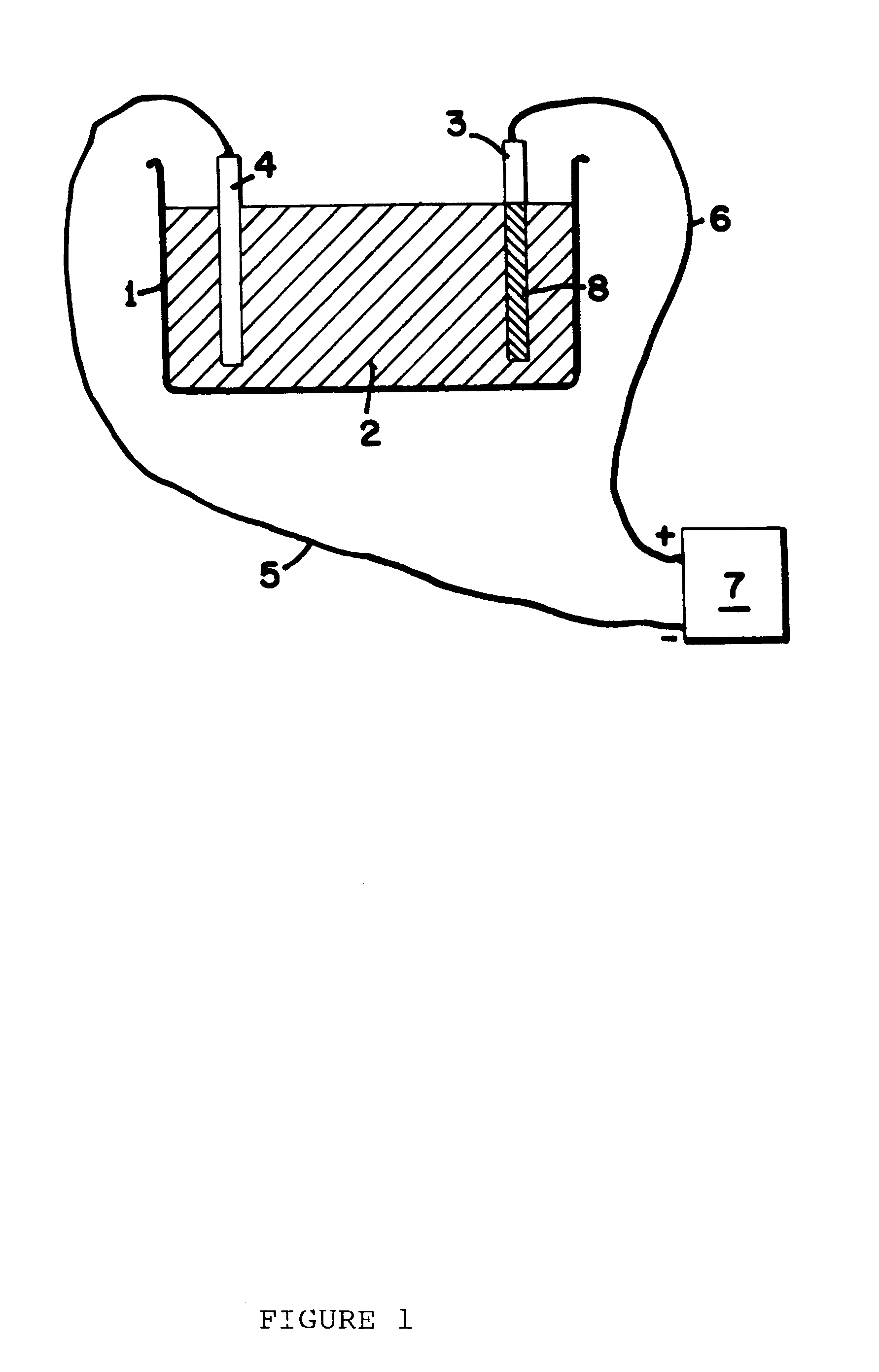
An AM50 magnesium component was anodised at 100 amps per square meter, up to an endpoint voltage of 350V DC. The electrolyte composition was 3% ammonia (expressed as w / v ammonia gas) and 0.2 molar diammonium hydrogen phosphate. The component received a rinse prior to anodization but no other pre-treatment. Upon attainment of the endpoint voltage, the power was maintained to the sample and held at 350V DC for approximately ten minutes. Upon rinsing the sample was found to have an anodic film of approximately 17 microns. The cycle time was approximately 30 minutes.

example 3

An AZ91D magnesium plate was anodised in an electrolyte comprising ammonia at 8% concentration (w / v as ammonia gas) and phosphoric acid at 0.1 molar. The sample was pre-cleaned in a bath comprising 0.2 molar sodium tetraborate and 0.07 molar sodium pyrophosphate at 60EC for five minutes, then it was activated in a bath comprising 35% hydrofluoric acid (v / v) for one minute prior to anodization. The anodization was conducted at 200 amps per square meter, using a DC power supply that attained 465V which was then held for five minutes. A coating of 21.8 microns resulted. The anodizing cycle required a total of 26 minutes.

EXMAPLE 4

An AZ91D magnesium plate was anodised in an electrolyte comprising ammonia at 5.0% (expressed w / v as ammonia gas), 0.1 molar phosphoric acid and 0.03 molar hydrogen peroxide. The plate was pre-cleaned as per example #3 above and activated as per example #3 above. It was then anodised using a power supply comprising a DC voltage that reached 385V, and an AC volt...

example 5

An AZ91D test plate was pre-cleaned in a bath comprising 0.2 molar sodium tetraborate and 0.07 molar sodium pyrophosphate as in example #3 above. It was then anodised in an electrolyte comprising 2.5% ammonia (expressed as ammonia gas) and 0.5 molar diethylene triamine (DETA), together with phosphoric acid at 0.1 molar, at a DC voltage that attained 360V which was held for five minutes. The current density was 200 amps per square meter. The plate was found to have an anodic coating of 28.2 microns. The total cycle time was 21 minutes for the anodizing process.


PUM

PropertyMeasurementUnit
temperatureaaaaaaaaaa
DC Voltageaaaaaaaaaa
AC Voltageaaaaaaaaaa

Abstract

This invention provides a method for the anodization of magnesium or magnesium based alloys using an electrolytic solution containing ammonia, amines or both. The use of such an aqueous electrolytic solution in at least preferred forms alters the conditions under which anodization can occur to provide a more than satisfactory coating on the magnesium material with reduced cycle times.

Description

This invention relates to a method for the anodization of magnesium and magnesium based alloys and products produced by that method.DESCRIPTION OF THE PRIOR ARTA major component of the building industry and, in particular, although not solely, the metal joinery industry has been aluminum based products. Although the price of aluminum has increased in recent years, it is still the principal material of many components due to its strength, weight and the finishes available to aluminum.By contrast, magnesium prices has remained relatively stable and is not a serious competitor to aluminum. It exhibits similar properties in terms of strength and weight. In the case of both aluminum and magnesium, these materials require some form of corrosion resistant and wear resistant coatings. Both materials easily discolor upon exposure to the atmosphere through oxidization.The anodization of aluminum is a relatively easy procedure compared with the equivalent anodization of magnesium. It is for th...

Claims


Application Information

Patent Timeline
Patent Type & Authority Patents(United States)
IPC IPC(8): C25D11/02C25D11/30
CPCC25D11/30
Inventor BARTON, THOMAS FRANCISMACCULLOCH, JOHN ARNOLDROSS, PHILIP NICHOLAS
Owner MAGNESIUM TECHNOLOGY LIMITED
Why Eureka
Try Eureka