Quasi-isothermal Brayton cycle engine

a brayton cycle, quasi-isothermal technology, applied in the direction of positive displacement liquid engines, special engines, liquid fuel engines, etc., can solve the problems of low power density, difficult to achieve perfect erickson cycles, and low efficiency of otto cycle engines

Inactive Publication Date: 2002-01-08
TEXAS A&M UNIVERSITY
View PDF54 Cites 74 Cited by
  • Summary
  • Abstract
  • Description
  • Claims
  • Application Information

AI Technical Summary

Problems solved by technology

The Otto Cycle engine is an inexpensive, internal combustion, low-compression engine with a fairly low efficiency.
In practice, a perfect Erickson cycle is difficult to achieve because isothermal expansion and compression are not readily attained in large, industrial equipment.
It features low power density, mechanical complexity, and difficult-to-achieve constant-temperature compressor and expander.
It has a higher power density than the Carnot cycle, but it is difficult to perform the heat exchange, and it is difficult to achieve constant-temperature compression and expansion.
In practice, real engines have "irreversibilities," or losses, associated with friction and temperature / pressure gradients.
These devices are generally suitable for aviation in which aircraft operate at fairly constant speeds; they are generally not suitable for most transportation applications, such as automobiles, buses, trucks, and trains, that must operate over widely varying speeds.
Further, the Otto and Diesel cycle engines lose efficiency because they do not completely expand high-pressure gasses, and simply throttle the waste gasses to the atmosphere.
There may, however, be some logistical constraints on obtaining salt-free water everywhere.
A drawback to using ceramics is the high material cost.
The engine, as a whole, is less efficient during these power bursts, but because the power bursts are usually only a small portion of the operating cycle, their effect on the overall efficiency of the system should be minimal.
The high temperatures in the tubular combustor causes carbon monoxide to be formed initially.
Unfortunately, backmixing promotes NO.sub.x formation because it increases the residence time of the gas.
The highly-polished multiple layers of nickel is a poor conductor, and will maintain heat from operation for a significant time.
The engine has a fixed compression ratio, but because the air inlet is choked, the compressor inlet is at a vacuum.
Because the compressor starts from a vacuum, the maximum pressure achieved by the compressor is less, which reduces the torque output of the engine.
Because of the irreversibilities associated with the throttle, this approach does not favor energy efficiency; however, it is very simple to implement.
More fuel raises the temperature, which increases the pressure, which increases the work per stroke.
The disadvantage to this approach is that operating under low torque means the engine temperature is lower, which reduces efficiency.
Some automobile designers might be reluctant to put high-pressure air tanks in the vehicle, so regenerative braking might not be incorporated into automobiles.

Method used


Image

  • Quasi-isothermal Brayton cycle engine
  • Quasi-isothermal Brayton cycle engine
  • Quasi-isothermal Brayton cycle engine

Examples


Embodiment Construction

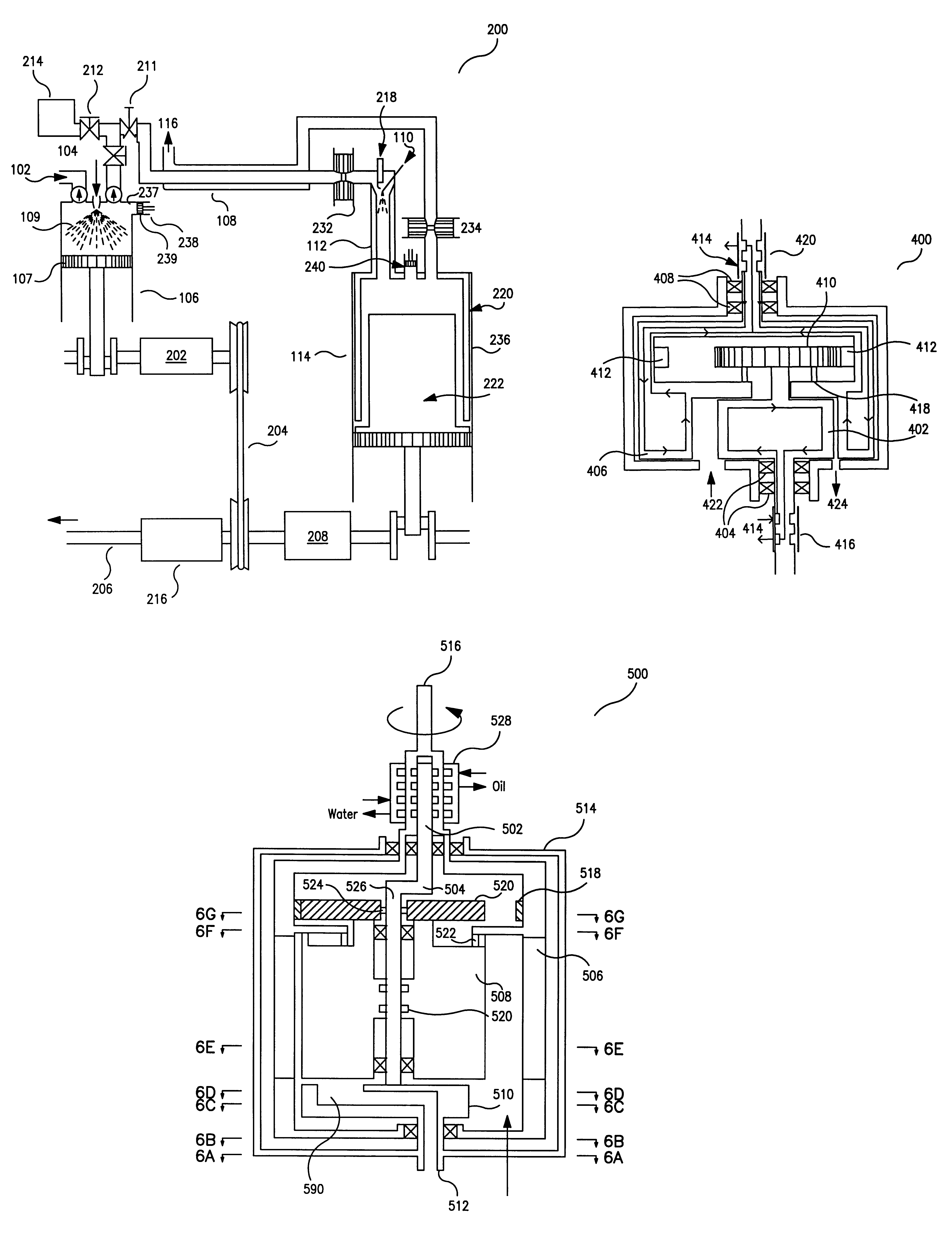
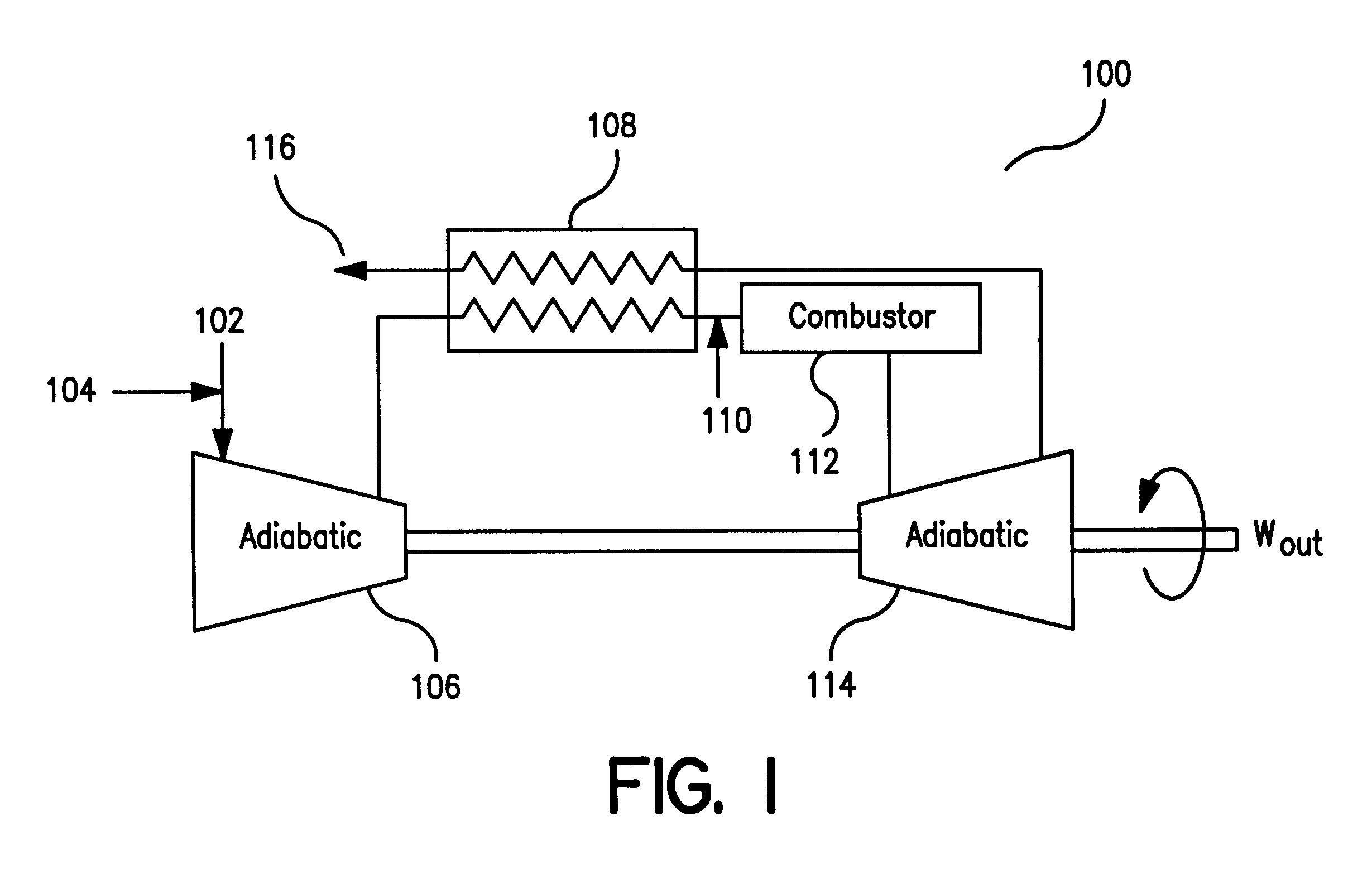
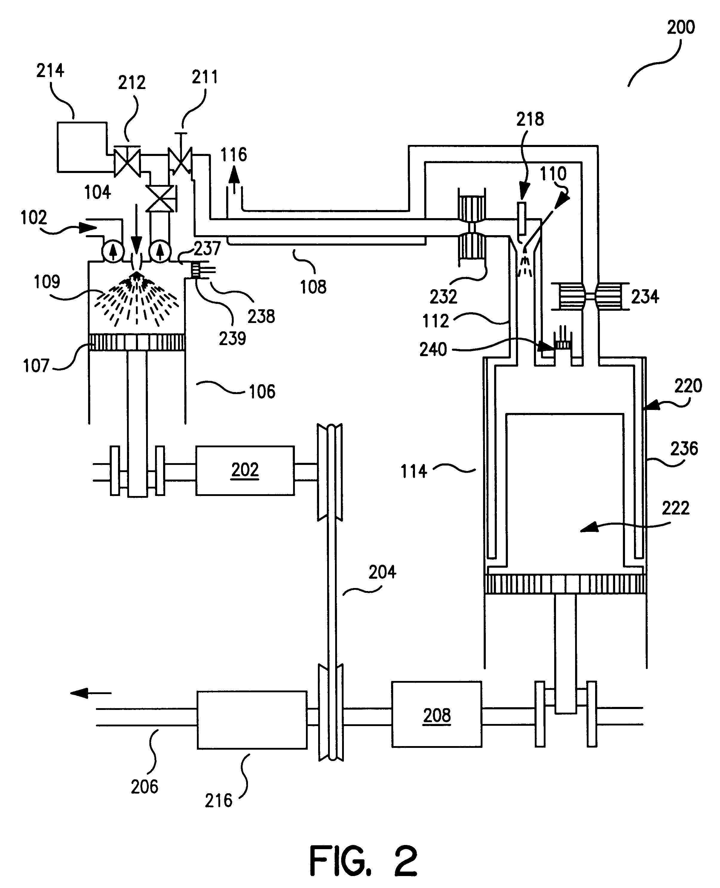
In order to facilitate a more complete understanding of the invention, an Example is provided below. However, the scope of the invention is not limited to specific embodiments disclosed in this Example, which is for purposes of illustration only.

Energy Efficiency

Table 1, below, summarizes the results of an efficiency analysis of an embodiment of the engine of the present invention. Three countercurrent heat exchangers were considered: stainless steel, high alloy and ceramic. Two approach temperatures were considered (50 and 100 K), both of which are easily achieved. Also, two compressor / expander efficiencies were considered: 0.7 and 0.8. (Note: compressor efficiency is calculated as the theoretical reversible power required assuming perfect water vaporization divided by the actual power required. Expander efficiency is calculated as the actual power production divided by the theoretical reversible power produced by an adiabatic expander). Depending upon the assumptions, the engine e...


PUM


Abstract

An engine is disclosed. According to one embodiment of the present invention, the engine comprises a compressor, and combustor, and an expander. The compressor compresses ambient air. The combustor burns the compressed air, and produces exhaust gasses. The expander receives the exhaust gases from the combustor, and expands the exhaust gasses. The compressor may be a gerotor compressor or a piston compressor having variable-dead-volume control. The expander may be a gerotor expander or a piston expander having variable-dead-volume control. In another embodiment, an engine comprises a piston compressor, a combustor, a piston expander, and a pressure tank. The piston compressor compresses ambient air. The combustor burns the compressed air, and produces exhaust gasses. The piston expander receives the exhaust gasses from the combustor, and expands the exhaust gasses. The pressure tank receives and stores the compressed air from the compressor. In another embodiment, a gerotor compressor or a gerotor expander comprises an inner gerotor, and an outer gerotor. The inner gerotor and the outer gerotor are driven so that they do not touch. The gerotors may be cantilevered or non-cantilevered.

Description

1. Field of the InventionThe invention relates generally to the field of power systems, and, more particularly, to a Quasi-Isothermal Brayton Cycle power system.2. Description of the Related ArtFor mobile applications, such as an automobile or truck, generally it is desirable to use a heat engine that has the following characteristics:Internal combustion to reduce the need for heat exchangers;Complete expansion for improved efficiency;Isothermal compression and expansion;High power density;High-temperature expansion for high efficiency;Ability to efficiently "throttle" the engine for part-load conditions;High turn-down ratio (i.e., the ability to operate at widely ranging speeds and torques;Low pollution;Uses standard components with which the automotive industry is familiar;Multifuel capability; andRegenerative braking.There are currently several types of heat engines, each with its own characteristics and cycles. These heat engines include the Otto Cycle engine, the Diesel Cycle e...

Claims


Application Information

Patent Timeline
Patent Type & Authority Patents(United States)
IPC IPC(8): F01C11/00F01C21/10F01C1/00F01C1/10F02B75/02F01C21/00F04C18/08F04C18/10F02G3/00F02G1/00F02G1/02F02G3/02F02B53/00F02C7/08F02B41/06F02C3/055
CPCF01C1/103F01C11/004F01C21/10F02B41/06F02G1/02F02G3/02F04C18/10F02B75/02F02B53/00Y02T10/17F02G2250/03F02G2254/11Y02T10/12
Inventor HOLTZAPPLE, MARK T.RABROKER, G. ANDREW
Owner TEXAS A&M UNIVERSITY
Why Eureka
Try Eureka