
Electrode rod for spark deposition, process for the production thereof, and process for covering with superabrasive-containing layer

a technology of electrode rods and electrodes, which is applied in the direction of metal-working apparatus, metallic material coating process, plasma technique, etc., can solve the problems of limited number of materials available for this purpose and the difficulty of electrode rod preparation

Inactive Publication Date: 2002-01-08
2 KANAGAWA +3
View PDF7 Cites 40 Cited by
  • Summary
  • Abstract
  • Description
  • Claims
  • Application Information

AI Technical Summary

Benefits of technology

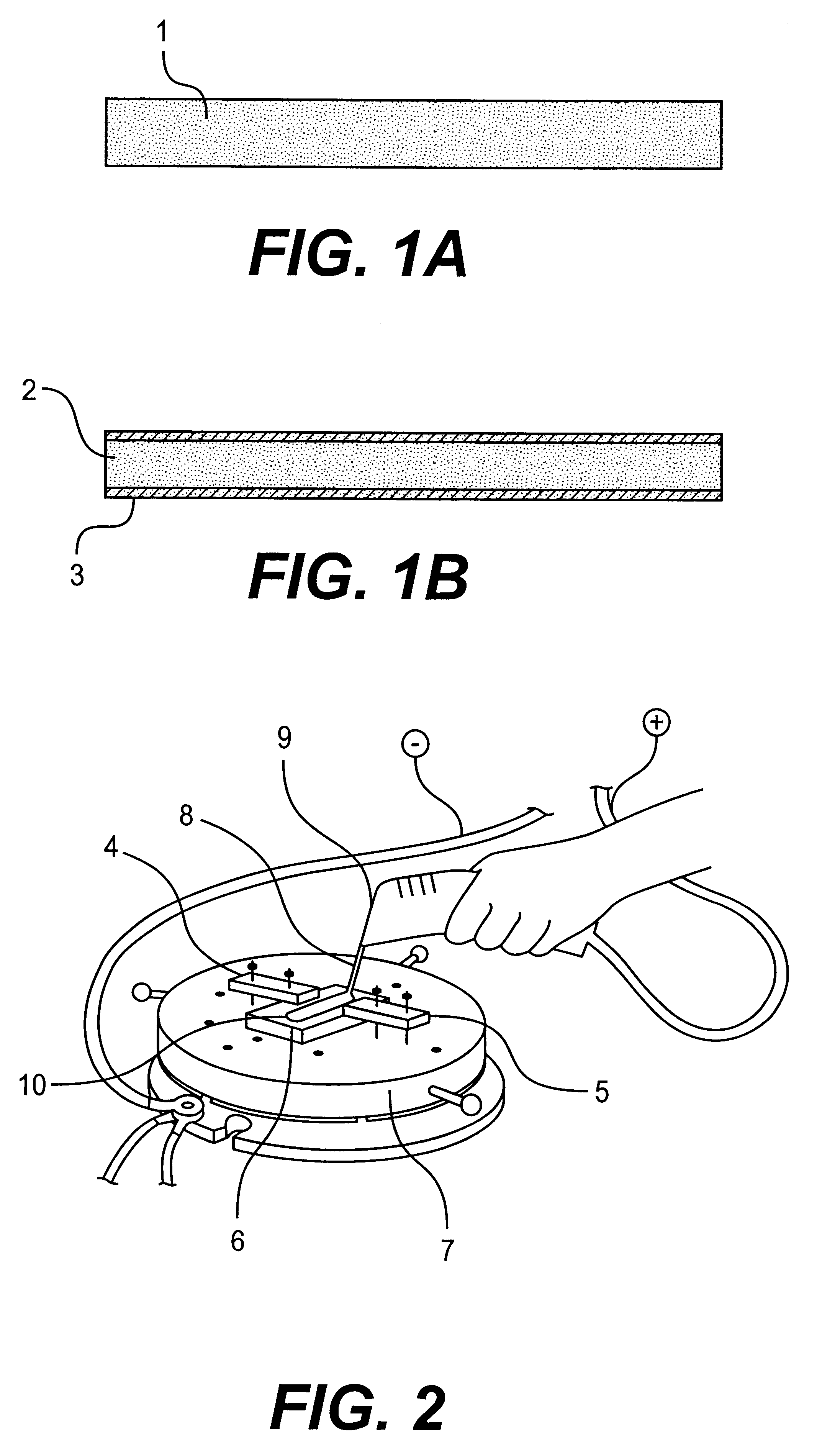
This invention provides a solution for those problems, described above, on the basis of a self-propagating high-temperature synthesis (SHS) as applied to the preparation of electrode rods. The invention essentially employs an electrode rod that is made of mixed powder of elemental materials so composed as to enable an SHS process. Thus the invention further provides a method, which consists of just simple basic steps, for the deposition of a coating of high-melting and hard-working material. Also provided is an electrode rod for such purpose.

Problems solved by technology

However there are a very limited number of materials available for this purpose since the inherent high melting points usually limit the rate of transfer to the work surface, and tend hardly to leave a deposit of regular composition.
Further the preparation of electrode rods involves some unsolved problems.

Method used


Image

  • Electrode rod for spark deposition, process for the production thereof, and process for covering with superabrasive-containing layer

Examples


example 1

A coating, of NiAl and TiN was formed on the work surface of a 30 by 30 by 5 mm block of GS6U nickel alloy, and both wear resistance per unit surface area and oxidation resistance were evaluated against the observed relative density (to the calculated value being 100) of the coating. Five electrodes were prepared using 100 volume parts of equimolar mixed powder of nickel and aluminum, which was admixed with 30 parts of TiN, and formed into compacts in a metallic die. The relative density of the rods was varied by means of the temperature they were fired. The discharge energy input and the deposition rate were fixed at 0.3 J and 1 cm.sup.2 per minute, respectively. The were lightly vibrated at 100 Hz relative to the work surface, while an estimated 10.mu.m gap, approximately, was maintained during the discharge between the work surface and electrode tip.

The wear resistance was examined in the grinding of corresponding sample blocks with a specific diamond wheel and evaluated as the l...

example 2

The relationship was determined between the discharged energy and resulting deposit thickness and continuity in several cycles of ESA-SHS process. The electrode rod was made up of equimolar mixed powder of Fe and Al, admixed with 35 vol. % TiB.sub.2 powder, formed at an 80% relative density. Coatings were deposited in argon at a rate of 1 cm.sup.2 per minute.

example 3

Electrode rods were prepared from an equimolar mixed powder of Ni and Al, admixed with 30 to 40 .mu.m diamond. Coatings were deposited in argon at a rate of 1 cm.sup.2 per minute, and evaluated in wear resistance of the deposited coatings. The test was conducted with GS6U nickel alloy works, as example 1, at a fixed energy input of 0.1 J. The wear resistance was evaluated by the same procedures as in example 1.


PUM

PropertyMeasurementUnit
melting pointaaaaaaaaaa
sizeaaaaaaaaaa
sizeaaaaaaaaaa

Abstract

An aspect of this invention is an electrode rod for spark alloying, comprising a compact of a first powder of a first component which comprises a metal selected from a group of Fe, Co, Ni, metals of 4a, 5a and 6a of the periodic table and Si, and a second powder of a second component which is capable of self-propagating high temperature synthesis to form with said first component carbide, nitride, boride, silicide or intermetallic compound, said first and second powders being mixed intimately with each other and formed into an axial rod. Another aspect is a method for the production of the electrospark alloying rod, comprising: mixing intimately a first powder of first component and a second powder of second component, said first component comprising at least one selected from Fe, Co, Ni, metals of groups 4a, 5a and 6a, Sn, Zn, Pb, Al and Cu, said second component comprising materials capable of SHS process to form a refractory (or intermetallic) compound, compressing said mixture, followed or not by further firing, and thereby forming an axial body with a bulk density 0.50 to 0.86 time the theoretical values for the corresponding substances. Still another aspect is a method for the deposition of a coating on a work by causing and holding an electric spark between said electrode rod and work, whereby transferring the materials of said first and second components to the surface of said work, and depositing thereon as a layer or more layers of such compound.

Description

Electrode rod for spark alloying, process for preparing the same, and method of depositing a super abrasive containing, coatingThis invention relates to an electrode rod for spark alloying, process for preparing the same, and method of depositing a super abrasive containing coating.TECHNICAL BACKGROUNDThe electrospark alloying (ESA) technique is known for the deposition of a wear-resistant coating on the surface of a metallic article. It is based on the material transfer by and in an electronic spark formed between an electrode rod of hard refractory material and work, whereby the former is molten or evaporated at an intense and instantaneous temperature of 3000.degree. to 4000.degree. C. to transfer over and deposit a coating, on the surface of a work, which may be made of iron-, nickel-, or copper-based alloy, or titanium, tantalum or molybdenum metal. It is also known to transfer carbon from the electrode to form carbide of an ingredient transition metal of the work, in order to ...

Claims


Application Information

Patent Timeline
Patent Type & Authority Patents(United States)
IPC IPC(8): C23C4/06C23C26/00B22F3/00B22F3/23B22F5/00B22F5/12B23H9/00C22C1/05
CPCC23C26/00C23C4/06
Inventor KOIZUMI, MITSUEOHYANAGI, MANSHIHOSOMI, SATORULEVASHOV, EVGENY ALEXANDROVICHNIKOLAEV, ALEXANDER GENNADIEVICHKUDRYASHOV, ALEXANDER EVGENIEVICH
Owner 2 KANAGAWA
Learn More