Precision high speed magnetic coil driver circuit

a high-speed magnetic coil and driver technology, applied in pulse automatic control, pulse manipulation, pulse technique, etc., can solve the problems of voltage or current change, substantial difficulty in accurately supplying voltage or current to a reactive load, and difficulty particularly eviden

Inactive Publication Date: 2002-05-14
IBM CORP
View PDF6 Cites 4 Cited by
  • Summary
  • Abstract
  • Description
  • Claims
  • Application Information

AI Technical Summary

Problems solved by technology

Supplying accurate levels of voltage or current to a reactive load presents substantial difficulty when the rate of voltage or current change is large.
This circumstance is present and the difficulty particularly evident in arrangements for precision positioning devices (e.g. translation tables) or electromagnetic deflection of a charged particle beam where the beam must be deflected to impinge on different and often widely separated locations of the target at high speed.
Also, electrostatic deflection plates can be unreliable because of contamination from hydrocarbon deposits which are an unwanted but unavoidable byproduct of photoresist exposure.
This unwanted and unpredictable charge on the contaminated deflection plates can produce undesired and unpredictable deflections.
However, electromagnetic deflection yokes present a very large inductive load which must be driven with high current.
Of course, image errors are cumulative and effects of undershoot, overshoot and ringing must be held to a small fraction of the resolution of the overall electron beam exposure system.
A complicating factor in design of drivers for inductive loads is that amplifier circuits therein can easily become saturated.
High accuracy is generally achieved through feedback and rapid change of input signal can cause large error signals that can drive amplifier output to substantially the power supply voltage at whic

Method used


Image

  • Precision high speed magnetic coil driver circuit
  • Precision high speed magnetic coil driver circuit
  • Precision high speed magnetic coil driver circuit

Examples


Embodiment Construction

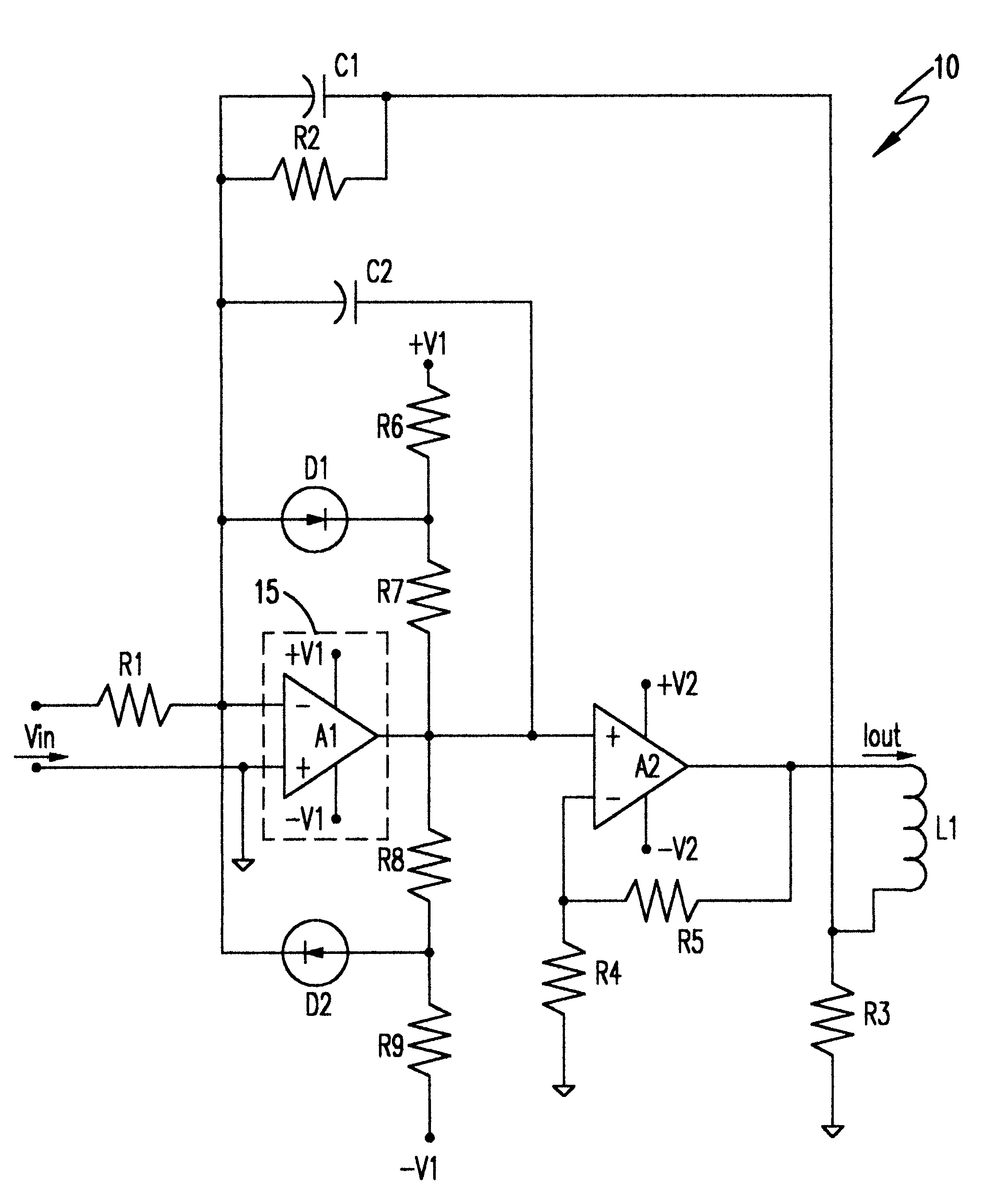
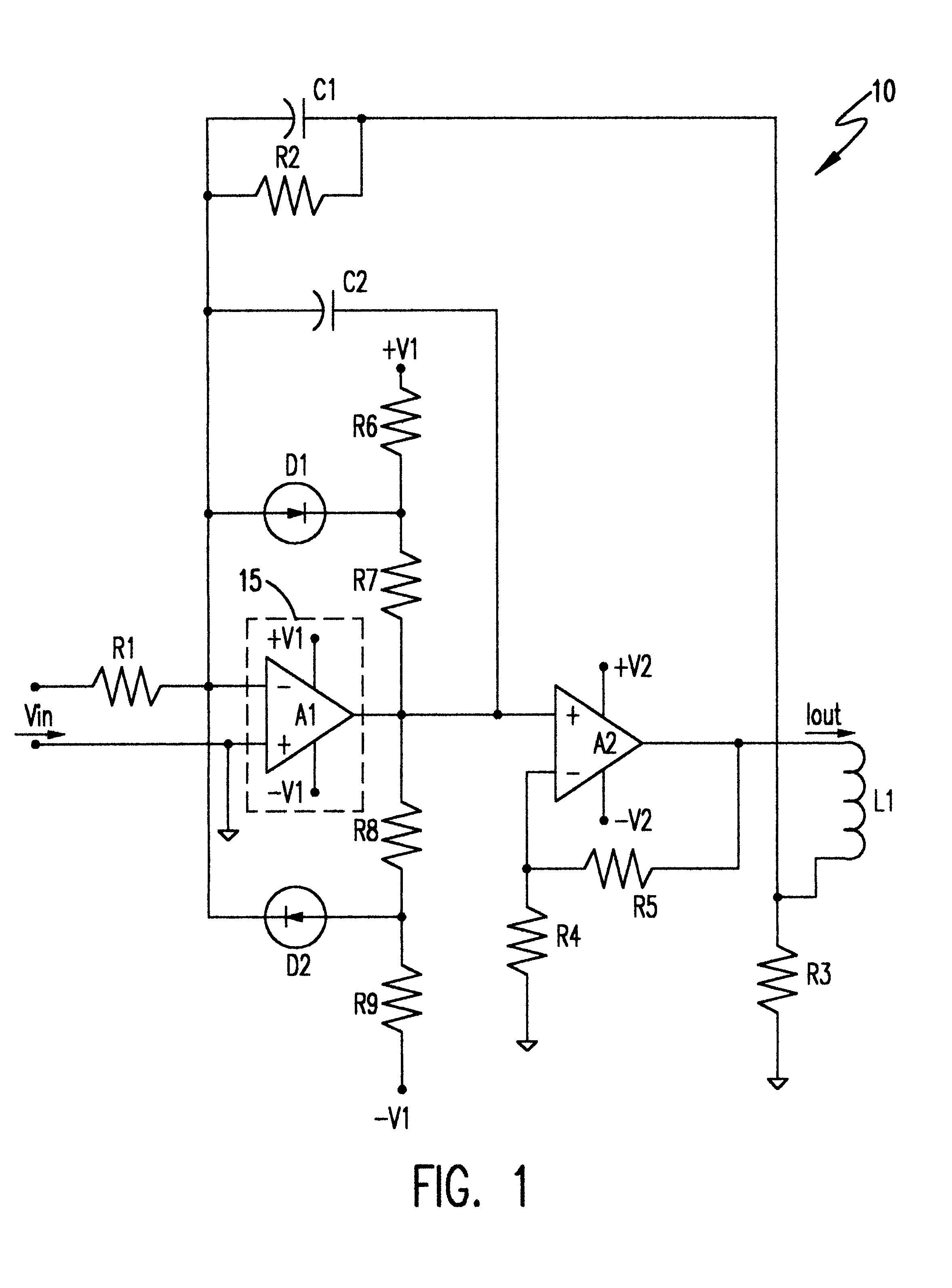
Referring now to the drawings, and more particularly to FIG. 1, there is shown a schematic diagram of a preferred embodiment of a driver circuit 10 in accordance with the invention. This circuit is intended to deliver a current through coil L1 which is proportional to an analog input voltage Vin with a very high accuracy within a very few parts per million. Precisely controlling the current through coil L1 has many useful applications, for example, voice coils of mechanical positioning systems and deflection yokes of charged particle beam systems. For convenience and as reflecting the preferred environment, the invention will be discussed in terms of its application to a deflection yoke of an electron beam lithography tool. However, it is to be understood that the applicability of the invention is not so limited.

The circuit of FIG. 1 includes two cascaded amplifiers A1 and A2 with the output of amplifier A2 being applied to the inductive load represented by coil L1. The current thro...


PUM


Abstract

Accuracy of correction of offset drift with temperature and noise are corrected in a high voltage, high current amplifier is improved by thermal isolation and/or temperature regulation of another amplifier having greater gain and connected to a different power supply in a closed loop feedback servo system. A clamping network connected to the higher gain amplifier to avoid hard saturation due to transient feedback signals from a reactive load, especially an inductive load, also prevents hard saturation of the high voltage, high current amplifier. An adjustable feedback circuit connected to the higher gain amplifier allows adjustment to obtain critical damping of a second order system and faster response to achieve proportionality of output current to input voltage with an accuracy of very few parts per million error and with minimum settling time.

Description

1. Field of the InventionThe present invention generally relates to voltage to current converter circuits suitable for driving high-inductance loads and, more particularly, to high speed, high precision coil drivers for electron beam lithography tools, precision cathode ray tubes and precision positioning systems.2. Description of the Prior ArtSupplying accurate levels of voltage or current to a reactive load presents substantial difficulty when the rate of voltage or current change is large. This circumstance is present and the difficulty particularly evident in arrangements for precision positioning devices (e.g. translation tables) or electromagnetic deflection of a charged particle beam where the beam must be deflected to impinge on different and often widely separated locations of the target at high speed. High speed of deflection or motion is necessary in cathode ray tubes to avoid luminance artifacts, such as image flickering, from being developed. In electron beam lithograph...

Claims


Application Information

Patent Timeline
IPC IPC(8): H03F3/343H03F3/347H03F3/45
CPCH03F3/347H03F3/45973H03F3/45475H03F2200/372
Inventor DORAN, SAMUEL K.ENICHEN, WILLIAM A.
Owner IBM CORP
Why Eureka
Try Eureka