Thermal barrier coating ceramic structure

a ceramic structure and thermal barrier technology, applied in the direction of non-positive displacement fluid engine components, liquid fuel engine components, efficient propulsion technologies, etc., can solve the problems of conventional ceramic coatings being prone to delamination at or near the nozzle, oxidizing and corroding,

Inactive Publication Date: 2002-09-24
MARIJNISSEN GILLION HERMAN +4
View PDF2 Cites 78 Cited by
  • Summary
  • Abstract
  • Description
  • Claims
  • Application Information

AI Technical Summary

Problems solved by technology

During gas turbine engine operation, hot section components such as combustors, turbine blade and vane airfoils, turbine frames, and exhaust nozzles are subject to oxidizing and corrosive, high temperature combustion effluent gas.
Despite efforts to optimize these varied approaches, both alone and in combination, advanced gas turbine engine efficiency is limited by the inability of the hot section components to achieve acceptable operating lives under increased mechanical and thermal loading.
Conventional ceramic coatings are prone to delamination at or near the ceramic/substrate interface due to differences in coefficients of thermal expansion between the relatively brittle ceramic and the more ductile superalloy substrate.
While conventional columnar ceramic topcoats have proven beneficial in use, they exhibit certain characteristics which inherently limit their operational performance and life regardless of the bond coat composition.
For example, since conventional columnar ceramic topcoats have a grain orientation direction which extends generally perpendicularly from the underlying substrate, the grains are relatively inelastic in the normal direction and exhibit poor impact strength, resulting in chipping when contacted by high speed sand grains and other foreign particulate matter ingested or released upstream during engine operation.
Erosion of the ceramic topcoat can also be a problem due to the cantilevered orientation of the columnar grains which are bonded to the alumina layer over a small surface area relative to their volume.
Accordin

Method used


Image

  • Thermal barrier coating ceramic structure
  • Thermal barrier coating ceramic structure
  • Thermal barrier coating ceramic structure

Examples


example 1

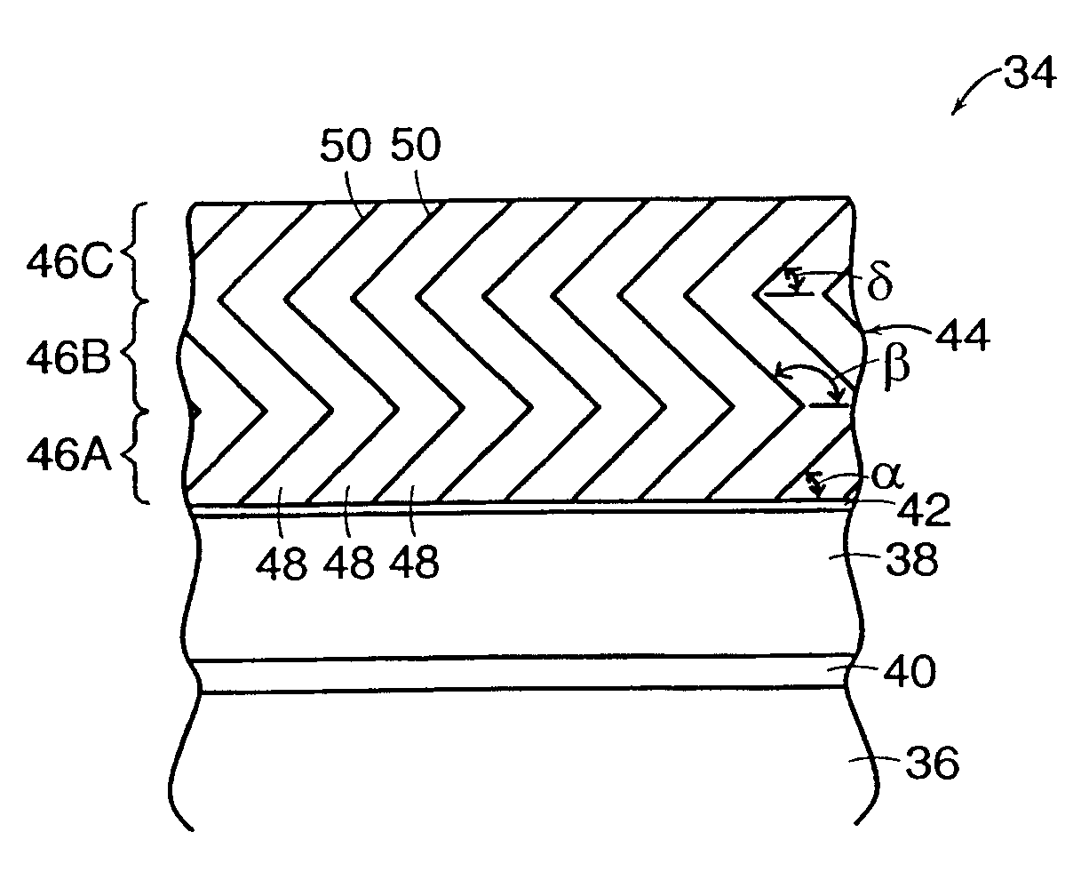
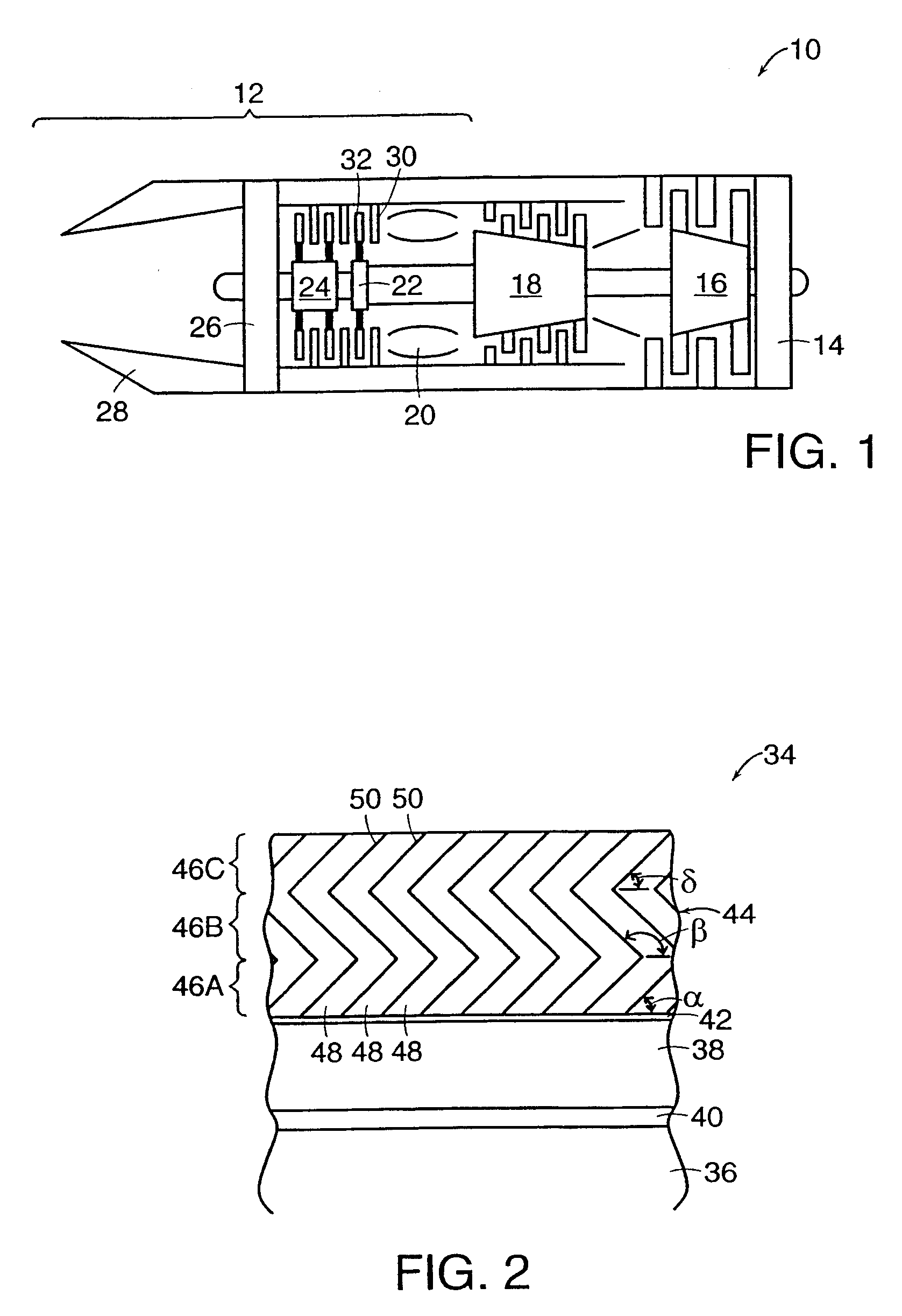
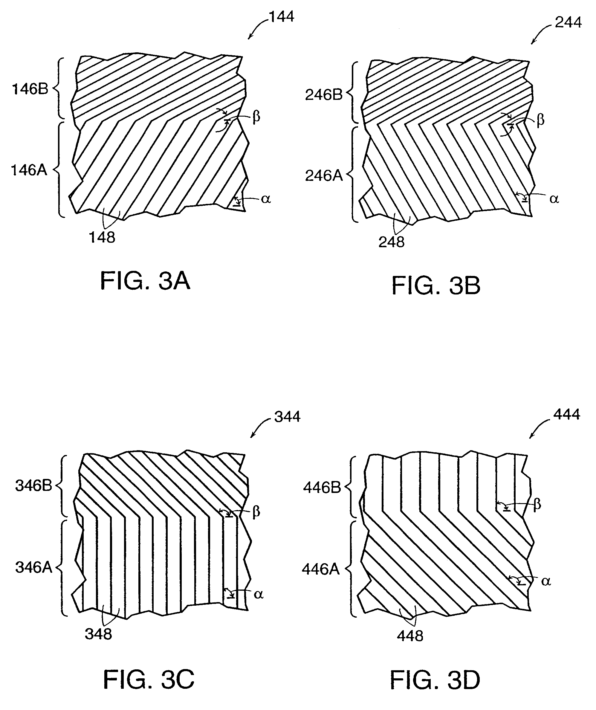
Test samples of cast CMSX2 single crystal material were coated with about a 50 .mu.m thick platinum aluminide bond coating and heat treated in a vacuum to adjust the surface concentration of aluminum to between about 20 weight percent and about 24 weight percent. Each sample was placed in a modified EB-PVD coating apparatus and preheated to about 850.degree. C. by an electron beam. A first columnar ceramic topcoat layer was applied by orienting the sample at a first predetermined angle substantially perpendicular to an ingot having a composition of ZrO.sub.2 --8%Y.sub.2 O.sub.3. The sample was maintained in this orientation and rotated at a rate of about 25 rotations per minute ("rpm") for a total period of about one minute while the ingot was vaporized by an electron beam with a power of about 38 kW. The resulting ceramic vapor cloud condensed on the preheated sample producing a first columnar layer substantially perpendicular to the platinum aluminide bond coat and underlying subs...

example 2

Test samples of Hastelloy X with an LPPS bond coating were pre-treated by ceramic peening, vibro-polishing, and cleaning. Each sample was placed in a modified EB-PVD coating apparatus and preheated to about 850.degree. C. by an electron beam. A first columnar ceramic topcoat layer was applied by orienting the sample at a first predetermined angle of about negative 45 degrees relative to an orientation normal to an ingot. The sample was maintained in this orientation for a total period of about one minute while the ingot having a composition of ZrO.sub.2 --8%Y.sub.2 O.sub.3 was vaporized by an electron beam with a power of about 38 kW. The resulting ceramic vapor cloud condensed on the preheated sample producing a first columnar layer having a grain orientation direction angle of close to about 135 degrees relative to the bond coating and underlying substrate. The sample was then alternatively reoriented to angles of about positive 45 degrees and back to negative 45 degrees relative ...


PUM

PropertyMeasurementUnit
Structureaaaaaaaaaa
Microstructureaaaaaaaaaa

Abstract

A multilayered ceramic topcoat of a thermal barrier coating system is useful for high temperature corrosive applications such as hot section components in gas turbine engines. The ceramic topcoat includes at least two layers, each having generally columnar grain microstructures with different grain orientation directions. A preferred method of producing the multilayered ceramic topcoat includes positioning a superalloy substrate at a first angled orientation relative to a ceramic vapor cloud in an electron beam physical vapor deposition apparatus for a time sufficient to grow a first ceramic layer. The substrate is then reoriented to a second, different angled orientation for a time sufficient to grow a second ceramic layer. The ceramic layers exhibit columnar microstructures having respective grain orientation directions which are related to the first and second substrate orientations. For uniformly coating a complex contoured surface such as a turbine blade airfoil, the blade can be rotated during coating deposition at each angled orientation. Alternatively, the article may be continuously reoriented according to a predetermined speed cycle to produce generally arcuate, sinusoidal, helical, or other columnar grain microstructures.

Description

The present invention relates to protective coatings for metallic articles and more particularly to an improved ceramic topcoat of a thermal barrier coating system for superalloy substrates.BACKGROUND INFORMATIONDuring gas turbine engine operation, hot section components such as combustors, turbine blade and vane airfoils, turbine frames, and exhaust nozzles are subject to oxidizing and corrosive, high temperature combustion effluent gas. Because these components often are subjected concurrently to high magnitude thermally and mechanically induced stress, the art has developed a variety of techniques in the design and manufacture of these components to ensure maintenance of structural and metallurgical integrity throughout the operating range of the engine. For example, components typically are manufactured from material compositions such as nickel- and cobalt-base superalloys having desirable properties at elevated, operating range temperatures. In the case of turbine airfoils, the...

Claims


Application Information

Patent Timeline
IPC IPC(8): B32B18/00C23C14/08C23C14/50C23C28/04C23C14/22
CPCB32B18/00C23C14/226C23C14/505C23C28/04C23C28/3215C23C28/345C23C28/3455C23C28/36C23C14/083Y10T428/12618Y02T50/67C04B2235/6562C04B2235/6581C04B2237/123C04B2237/343C04B2237/345Y10T428/12549Y10T428/1259Y02T50/60
Inventor MARIJNISSEN, GILLION HERMANVAN LIESHOUT, ASTRID HELENNIA FRANCOISETICHELER, GERARDUS JOHANNESBONS, HENDRIKUS JACOBUS MARIARIDDER, MICHIEL LEENDERT
Owner MARIJNISSEN GILLION HERMAN
Why Eureka
Try Eureka